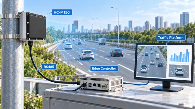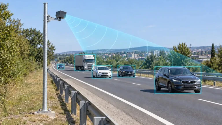
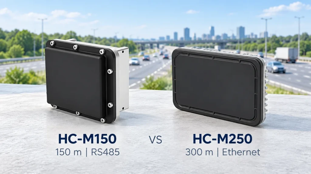
Choose HC-M150 first when your project needs multi-lane vehicle detection within its nominal 150-metre range and an RS485 connection. Choose HC-M250 first when the monitoring area extends beyond that distance, up to its published 300-metre maximum, or when Ethernet is a better fit for the roadside system.
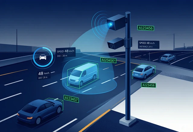
There is one important application distinction: HC-M150 can be evaluated for radar-assisted speed-enforcement integration, while HC-M250 is positioned for traffic monitoring and control, not traffic enforcement.
These are starting recommendations, not a claim that one model is universally better. This traffic radar selection guide explains how to make the choice from the road layout, required data and existing controller.
1. HC-M150 vs HC-M250 at a glance
| Selection factor | HC-M150 | HC-M250 |
|---|---|---|
| Published detection range | 150 m nominal | 10–300 m |
| Communication | RS485, 115200 baud | Ethernet |
| Road coverage | Up to 8 lanes, two-way monitoring | Up to 8 lanes, two-way monitoring |
| Simultaneously tracked targets | Up to 64 | Up to 128 |
| Target-data update time | 50 ms | 70 ms |
| Power supply | 12 V DC | 12–24 V DC |
| Application direction | Traffic monitoring and radar-assisted speed-enforcement integration | Long-range traffic monitoring, signal control and vehicle-road coordination |
These figures are for initial selection. The HC-M150 product page and HC-M250 product page provide the corresponding specifications. Neither range nor lane coverage should be treated as an unconditional guarantee at every installation position.
2. Select the required road section, not the largest range number
Define where detection must begin and end, and where the application actually uses the data. A counting point, camera measurement area and long approach-monitoring corridor can have different coverage requirements.
For example, if the required measurement area is around 80 metres from the mounting position and the controller already accepts RS485 data, HC-M150 is a sensible first candidate. A longer-range model is not automatically necessary.
If a monitoring project needs vehicle tracks approximately 220 metres away, start the evaluation with HC-M250. Do not select the shorter-range model and assume that software settings will extend its published capability.
Check the nearest required detection point as well as the farthest one. A specification with a defined minimum distance must not be interpreted as continuous coverage all the way back to the pole.
Also check sight lines. A vehicle hidden behind a truck, structure or road crest does not become visible simply because the selected radar has a higher maximum-range figure.
3. Match the interface to the existing controller
Before selecting either model, ask the system integrator which interfaces the host hardware actually provides and whether its software already supports the relevant radar output.
An existing serial-based installation may benefit from staying with a supported RS485 workflow. A network-oriented roadside cabinet may favour Ethernet. However, the presence of a matching socket is only the beginning of integration.
The receiver still needs to interpret the device-specific messages, map data to the application and handle interrupted communication. Ethernet does not automatically mean a standard web API, and RS485 does not automatically mean Modbus compatibility.
A suitable gateway can bridge a serial device into a networked architecture, but this adds hardware, configuration and support work. Compare the complete system design rather than assuming that an adapter eliminates every interface difference.
Do not assume that HC-M150 and HC-M250 share the same protocol or that an existing decoder can be reused unchanged. Request documentation for the selected model before committing development resources. The HC-M150 RS485 integration guide explains the serial-based workflow without publishing proprietary message definitions.
4. Do not choose by lane count or target capacity alone
Lane count is a useful screening condition, but it is not a complete description of a road. Two sites with the same number of lanes can differ in width, curvature, mounting offset, traffic direction and obstruction.
Provide a road cross-section and the intended mounting position. Confirm that the required lanes can be observed at the actual measurement area, not merely that the catalogue lane count is sufficient.
Target capacity is another separate factor. A larger tracking capacity is not evidence of proportionally higher counting accuracy. Estimate how many targets may be present at the same time, then validate the application with representative traffic.
Update time should also be considered in context. A fast update does not, by itself, establish a faster complete system: controller processing, buffering, network transport and application logic can all contribute delay.
5. Separate monitoring from speed-enforcement requirements
A traffic-monitoring platform may use speed as one input for congestion analysis or reporting. A radar-assisted enforcement system must additionally associate the measurement with the correct vehicle and coordinate the camera and evidence workflow.
These are not the same procurement task. A long-range monitoring radar should not be selected for enforcement simply because its output includes vehicle speed.
For an enforcement-related project, specify the measurement area, required speed performance, vehicle association, timing and acceptance requirements before selecting the sensor. Any required calibration and approvals must be checked for the intended deployment; a product comparison is not a statement of certification.
See the speed enforcement integration solution for the broader controller-and-camera workflow.
6. Apply the comparison to your project
A counting site with an existing serial controller
Start with HC-M150 if its coverage meets the defined measurement area and the receiving system can support its output. Validate lane assignment and passage counts before extending the test to the full installation.
A longer approach-monitoring corridor
Start with HC-M250 where the required observation distance is outside the shorter-range option. Check the entire useful corridor, including the nearest required detection point, rather than demonstrating only one distant vehicle.
A short monitoring section in an Ethernet-based cabinet
HC-M250 may still be a practical candidate even when long range is not the main requirement. Compare its fit with the cost and maintenance implications of adding a serial gateway. A shorter road section does not automatically rule it out.
A camera-linked speed-measurement project
Evaluate HC-M150 against the complete measurement and camera requirements. Do not substitute HC-M250 solely for its longer range. Confirm the intended application with the technical team before ordering.
For non-enforcement monitoring, the traffic flow monitoring solution provides additional system context.
7. Compare performance using the same acceptance test
If both candidates appear suitable, use one written acceptance plan rather than comparing isolated catalogue numbers.
Specify the same road section, vehicle mix, operating conditions, reference method and data-quality criteria. Check missed and duplicate passages, lane assignment, track continuity and communication availability according to the application.
Do not directly rank percentage-based and absolute speed-error specifications without confirming their definitions and test conditions. Likewise, do not treat detection range, position accuracy and target separation as interchangeable measurements.
Compare total integration effort as well: receiver development, power arrangements, cabling, gateways, configuration and ongoing maintenance. This guide does not assume that either model is always the lower-cost choice.
8. What to send before requesting a recommendation
A useful project brief should include:
- The application: traffic counting, monitoring, signal control, vehicle-road coordination or camera integration.
- A road photograph or drawing, including lane widths and traffic directions.
- The proposed mounting position, height and major obstructions.
- The nearest and farthest required detection points.
- The required target data, traffic statistics and collection intervals.
- The existing controller, available interfaces and platform requirements.
- The available power supply and proposed acceptance criteria.
The practical choice is the model that meets this brief with a workable installation and integration path, not simply the model with the largest number in its name.
Send your project requirements through the HC-M150 enquiry form or HC-M250 enquiry form. Our technical team can review the road layout and data requirements before recommending a model.