Analysis of the Working Principle and Application Scenarios of Radar Level Sensor

In the era of booming industrial automation and intelligent manufacturing, level measurement technology, as a crucial part of the industrial production process, has always occupied a key position. According to the latest report released by MarketsandMarkets, the global level instrument market size exceeded the $5 billion mark in 2023. Among numerous level measurement devices, radar level sensor stand out, leading the market with an average annual growth rate of 8.2%. This non – contact measurement device based on the principle of electromagnetic waves, with its excellent measurement accuracy of up to ±1mm and strong adaptability to operate stably under extreme conditions ranging from – 200°C to + 400°C, is gradually revolutionizing the measurement system of the process industry. The following article will deeply and comprehensively analyze the core technical principles of radar level sensor and explore their unique value in different industrial scenarios.

I. In – depth Analysis of Technical Principles

1.1 Electromagnetic Wave Propagation Theory

The core operation of radar level sensor is based on the electromagnetic wave propagation laws described by Maxwell’s equations. The microwaves emitted by the sensors typically have frequencies of 6GHz, 26GHz, or 80GHz. When these microwaves propagate to the interface between air and a medium, they will be reflected in accordance with Snell’s law. The degree of reflection is mainly determined by the dielectric constant of the medium. Generally, for liquids with a dielectric constant ε_r > 1.4, take crude oil as an example, its dielectric constant ε_r = 2.1. Such liquids can reflect more than 10% of the transmitted power of microwaves. Such a high reflection energy provides a solid guarantee for reliable detection, enabling the sensor to accurately capture the reflected signal and laying the foundation for subsequent measurement work.

1.2 Time – Domain Reflectometry (TDR)

Pulse – type radars adopt advanced nanosecond – level ultra – short pulse (<1ns) technology. It calculates the distance between the sensor and the measured object by accurately measuring the time difference ΔT between the transmitted wave and the received echo. The calculation formula is D = c×ΔT/(2√ε_r), where c is the propagation speed of electromagnetic waves in a vacuum. For example, the 80GHz high – frequency sensor developed by the German company VEGA has an extremely high time resolution of up to 3.3ps. This excellent performance enables its distance resolution to reach 0.5mm. With such high precision, it can achieve millimeter – level accuracy in liquid – level measurement in scenarios with strict requirements for measurement accuracy, such as LNG storage tanks, effectively meeting the needs of high – precision measurement in industrial production.

1.3 Frequency – Modulated Continuous Wave (FMCW) Technology

FMCW – type sensors use linear frequency – modulation technology. Take the case of the 26GHz frequency band with a 2GHz bandwidth. It generates a signal with a continuously changing frequency. The frequency difference Δf between the received echo and the transmitted wave has a linear relationship with the liquid – level distance. The specific formula is Δf = (B×2D)/(c×T_m), where B represents the bandwidth and T_m is the modulation period. One of the significant advantages of this technology is its strong anti – interference ability. In a strong – interference environment, its signal – to – noise ratio can reach more than 80dB. This enables it to still measure the liquid level stably and accurately in complex environments such as industrial sites with a large amount of electromagnetic interference.

1.4 Signal Processing Innovation

Modern radar level sensor integrate DSP digital signal processors and adopt multiple echo tracking algorithms (MET) and adaptive filtering technology. The 5708 series of products from American company Rosemount is a typical example. This series of products can accurately identify the true liquid surface even when the foam layer thickness reaches 2 meters through FFT spectrum analysis technology. After actual testing, its misjudgment rate is lower than 0.01%, greatly improving the accuracy and reliability of measurement and effectively avoiding measurement errors caused by foam interference.
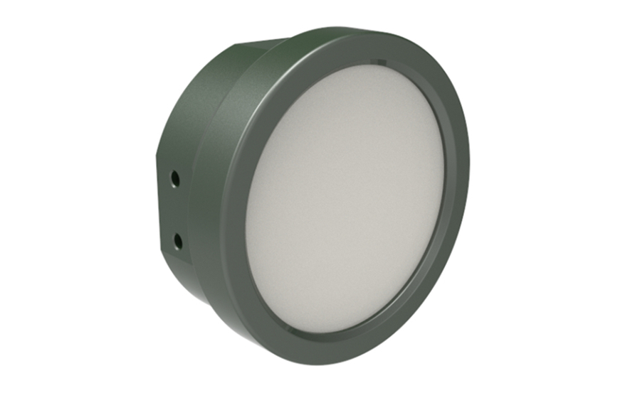
radar level sensor


II. Product Types and Technological Evolution


Type Frequency Range Measurement Range Typical Accuracy Applicable Scenarios
Pulse Radar 6 – 26GHz 0 – 70m ±3mm Crude oil storage tanks, cement silos
FMCW Radar 24 – 26GHz 0 – 30m ±1mm Chemical storage tanks, reactors
Guided – Wave Radar 1 – 2GHz 0 – 6m ±0.5mm Viscous media, small – range measurement
80GHz Radar 78 – 82GHz 0 – 120m ±1mm LNG storage tanks, large silos

Technological Evolution Trends:

  • High – frequency: The market share of 80GHz products increased from 12% in 2018 to 35% in 2023.
  • Intelligence: Siemens’ SITRANS LR560 integrates AI algorithms to automatically identify false echoes.
  • Multi – parameter measurement: The E + H FMR67 series can simultaneously measure the liquid level, interface, and medium temperature.

III. Panoramic Analysis of Industrial Application Scenarios

3.1 Energy and Chemical Industry

In a 20,000m³ crude oil storage tank, an 80GHz radar sensor achieves a measurement accuracy of ±2mm. With a triple – redundant configuration in line with API 2350 standards, it ensures the safe operation of an oil depot with an annual turnover of 5 million tons. A case shows that a refinery uses a guided – wave radar to measure the asphalt liquid level (ε_r = 2.3), and it has been operating continuously for 5 years without failure under a working condition of 150°C.

3.2 Food and Pharmaceutical Industry

It adopts a PTFE sealing structure certified by the FDA to meet 3D cleaning requirements. In the application of fermentation tanks, FMCW radars can overcome steam interference (humidity 100%RH) and control the measurement deviation within ±3mm. After a dairy enterprise used a 26GHz radar, the CIP cleaning cycle was extended from 3 times a week to 1 time a week.

3.3 Environmental Protection and Water Treatment

In a secondary sedimentation tank with a diameter of 40 meters, a pulse radar realizes a measurement range of 0 – 15 meters and has an anti – surface foam capacity of 1.5 – meter thickness. A case from a sewage treatment plant shows that compared with traditional ultrasonic sensors, the maintenance cycle of radar instruments has been extended from 3 months to 3 years.

3.4 Challenges in Special Working Conditions

  • High – temperature and high – pressure: Shell Pernis Refinery uses a radar with a ceramic antenna when facing extreme high – temperature and high – pressure conditions of 380°C and 6MPa. The ceramic antenna has good high – temperature and high – pressure resistance, enabling the radar sensor to work normally in such harsh environments and achieve accurate liquid – level measurement.
  • Strongly corrosive environment: When measuring the liquid level of a 98% sulfuric acid storage tank, Formosa Plastics Group uses a radar sensor with a Hastelloy C276 antenna considering the strong corrosiveness of sulfuric acid. Hastelloy C276 has excellent corrosion resistance, effectively ensuring the service life and measurement accuracy of the radar sensor in a strongly corrosive environment.
  • Vacuum environment: In the semiconductor industry, the liquid – level measurement in a vacuum chamber of 10^-5Pa has special requirements. Therefore, specially designed radar sensors are used in the industry. These sensors are specially designed and processed to operate stably in a vacuum environment and meet the liquid – level measurement requirements in the semiconductor production process.

IV. Future Technology Outlook

  • Photonic radar technology: The photon radar prototype developed by MIT in the United States has a measurement resolution reaching the 10μm level.
  • MIMO array antenna: Emerson launched an 8×8 array antenna, reducing the beam angle to 3°.
  • Digital twin integration: ABB Ability system realizes real – time mapping of sensor data and 3D models.
  • Energy self – supply: The energy harvesting module developed by TI can obtain 5mW of electrical energy from environmental vibrations.
According to ABI Research’s prediction, by 2028, intelligent radar sensors will account for 62% of the level instrument market, and their edge – computing capabilities can reduce data processing latency to less than 10ms.
Driven by the general trend of digital transformation, radar level sensor are no longer just single – function measurement tools; they are gradually evolving into key nodes in the industrial Internet of Things. Selecting an appropriate radar solution can significantly improve the benefits of enterprises. For example, it can increase the utilization rate of storage tanks by 15% and reduce maintenance costs by 40%. For enterprises committed to process optimization and intelligent upgrading, deeply understanding the internal logic of radar level technology, mastering its core principles and application key points will undoubtedly become an important technical advantage in the fierce market competition.