Frequency-modulated continuous-wave radar can measure both the range and radial velocity of a target. It does this by transmitting a sequence of frequency-changing signals known as chirps and comparing the transmitted signal with the delayed echo received from the target.
The basic principle sounds simple, but practical FMCW radar performance depends on chirp bandwidth, sweep time, sampling rate, carrier wavelength, observation time, antenna configuration, signal-to-noise ratio and target geometry. Maximum detection distance, range resolution and speed accuracy are therefore different specifications and should not be treated as the same measurement.
What Is FMCW Radar?
Continuous-wave radar transmits energy continuously rather than sending isolated pulses. A conventional single-frequency CW radar can use the Doppler shift to measure the radial velocity of a moving target, but it normally cannot determine absolute target range.
FMCW radar solves this limitation by changing the transmitted frequency over time. The most common waveform is a linear chirp, in which frequency increases or decreases at a controlled rate during each sweep.
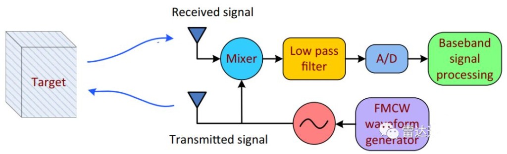
When the echo returns, it is delayed relative to the transmitted chirp. Mixing the transmitted and received signals produces a lower-frequency intermediate or beat signal. The frequency and phase of this signal contain information about the target’s range and motion.
The FMCW Chirp
A linear chirp is commonly described by three parameters:
- Bandwidth B: the total frequency change during one chirp.
- Chirp duration Tc: the time required to complete the sweep.
- Chirp slope S: the rate at which frequency changes.
The chirp slope is:
S = B / Tc
A wider bandwidth generally improves range resolution. Chirp duration and repetition timing influence maximum unambiguous velocity, velocity resolution and the time available for signal acquisition.
How FMCW Radar Measures Range
A target at range R produces an echo with a round-trip propagation delay:
τ = 2R / c
where c is the speed of light.
For a stationary target and a linear chirp, the range-related beat frequency is approximately:
fb = Sτ = 2SR / c
The corresponding range is therefore:
R = cfb / 2S
The radar samples the beat signal with an analog-to-digital converter. A range FFT separates the received signal into frequency bins, which are then converted into target ranges using the known chirp slope.
With multiple targets at different distances, the range spectrum can contain several peaks. Detection algorithms determine which peaks are likely to represent real targets rather than noise, interference or unwanted reflections.
Range Resolution Is Not the Same as Maximum Range
Range resolution describes the radar’s ability to distinguish two targets that are close together in distance. For an ideal linear FMCW waveform, the approximate range resolution is:
ΔR = c / 2B
This means that range resolution is primarily determined by sweep bandwidth. Increasing the number of FFT points can make the displayed spectrum smoother, but it does not create true physical resolution beyond the waveform bandwidth.
Maximum measurable range is governed by different factors, including:
- Maximum beat frequency accepted by the receiver and ADC
- Chirp slope
- Sampling rate
- Transmit power and antenna gain
- Receiver noise and processing gain
- Target radar cross section
- Required detection probability
The theoretical unambiguous range may consequently be longer than the distance at which a particular target can be detected reliably.
How FMCW Radar Measures Velocity
A moving target changes the phase and frequency of the received signal. The Doppler frequency associated with radial velocity is:
fd = 2vr / λ
or:
vr = λfd / 2
where λ is the radar wavelength and vr is the target velocity component directed toward or away from the radar.
Modern FMCW radar normally transmits multiple chirps in each measurement frame. Samples collected within a chirp are processed in the range dimension, while the phase progression across consecutive chirps is processed in the Doppler dimension.
This two-dimensional processing creates a range-Doppler map. Targets can then be separated by both distance and radial velocity.
Why Multiple Chirps Are Required
A single chirp can provide range information, but reliable velocity estimation normally requires observations across multiple chirps. A Doppler FFT analyzes how the target phase changes from one chirp to the next.
For a multi-target scene, this processing helps distinguish:
- Targets at different ranges
- Targets at the same range but different radial velocities
- Stationary objects and moving vehicles
- Approaching and receding targets
Longer coherent observation time generally improves velocity resolution. However, it also affects frame-update time and the radar’s ability to follow rapidly changing traffic scenes. Radar waveform design therefore involves trade-offs rather than one universally optimum configuration.
Velocity Resolution and Maximum Unambiguous Velocity
Velocity resolution depends mainly on carrier wavelength and coherent observation time. A longer observation across more chirps can separate targets with smaller velocity differences.
Maximum unambiguous velocity is influenced by the time interval between chirps. If the target phase changes too much between consecutive chirps, the measured Doppler phase can wrap and produce an ambiguous velocity.
Designing for a higher maximum unambiguous speed may require a shorter chirp repetition interval. Designing for finer velocity resolution generally requires a longer observation time. Both requirements must be balanced with range, update rate and processing capacity.
Range-Doppler Coupling
For a moving target, the measured beat signal contains contributions from both propagation delay and Doppler shift. A simplified single-chirp calculation can therefore couple range and velocity.
Triangular up-and-down sweeps can estimate range and velocity by comparing the beat frequencies from positive and negative chirp slopes. Modern traffic and automotive radar more commonly uses sequences of chirps and two-dimensional FFT processing to estimate range and Doppler separately.
The exact signal-processing method depends on the waveform architecture. It is therefore unsafe to apply a single simplified equation to every commercial FMCW radar.
Radial Velocity and Cosine Error
Radar directly measures radial velocity—the component of target velocity along the radar line of sight. If a vehicle moves at an angle θ relative to the radar beam, the measured component is:
vr = v cos(θ)
A large installation angle can cause the measured radial speed to be lower than the vehicle’s actual road speed unless the geometry is known and compensated correctly.
For traffic applications, mounting position, lane direction, road curvature and sensor alignment must therefore be included in commissioning. Signal processing cannot reliably correct an installation geometry that has not been measured accurately.
How Angle Is Estimated
Range and velocity alone do not identify the lateral position of a target. Radar systems with multiple receiving antennas can estimate arrival angle from the phase differences between antenna channels.
Combining range, Doppler and angle processing allows the radar to produce target-level information such as:
- Longitudinal distance
- Lateral position
- Radial velocity
- Estimated trajectory
- Lane assignment
Angular resolution depends on antenna aperture and array design. A larger number of virtual antenna channels can improve angular separation, but antenna count alone does not determine total radar performance.
From ADC Samples to a Target List
A practical FMCW radar processing chain commonly includes:
- Generation and transmission of a chirp sequence
- Reception and mixing of target echoes
- Low-pass filtering and analog-to-digital conversion
- Calibration and removal of unwanted static components
- Range FFT within each chirp
- Doppler FFT across multiple chirps
- Target detection on the range-Doppler map
- Angle estimation using multiple antenna channels
- Clustering and target tracking
- Output of coordinates, speed and trajectory data
The quality of the final target list depends on more than the RF waveform. Calibration, detection thresholds, clutter suppression, multipath handling, association logic and tracking algorithms all affect system performance.
Factors That Affect Real-World Measurement
Target radar cross section
Large vehicles normally produce stronger reflections than small or low-reflectivity targets. Detection range should therefore always be associated with a defined target type and probability of detection.
Multipath reflections
Road surfaces, barriers, signs and large vehicles can create indirect reflection paths. Multipath may produce false targets or disturb measured position if it is not addressed by installation design and signal processing.
Occlusion
A nearby truck can partially hide a smaller vehicle from the radar. Sensor height, lateral offset and viewing geometry influence how often this occurs.
Interference
Other radar transmitters operating nearby may raise the noise floor or create interference patterns. Waveform planning and interference mitigation become increasingly important in dense installations.
Vibration and alignment
Movement of the mounting structure can change the radar coordinate system. Rigid mounting and accurate alignment are essential for lane assignment and precise target positioning.
FMCW Radar in Traffic Applications
FMCW processing is used in a range of roadway systems, including:
- Multi-lane traffic monitoring
- Vehicle speed measurement
- Queue and congestion detection
- Traffic-signal control
- Speed enforcement integration
- Camera triggering and radar-video fusion
- Vehicle trajectory analysis
The WaveLogic HC-M250 traffic radar provides target data for long-range, multi-lane traffic monitoring and system integration. For system-level applications, see the traffic flow monitoring solution and the speed enforcement integration solution.
Frequently Asked Questions
Can FMCW radar measure distance and speed at the same time?
Yes. Range is obtained primarily from the beat-frequency relationship within each chirp, while radial velocity is normally estimated from phase changes across a sequence of chirps. Multi-dimensional processing separates the range and Doppler information.
Does a higher operating frequency automatically improve range accuracy?
No. Range resolution is primarily related to waveform bandwidth. Carrier frequency affects wavelength, Doppler sensitivity and antenna size, but it does not by itself determine range resolution or complete system accuracy.
Does a larger FFT improve the physical range resolution?
Not by itself. Zero-padding or increasing FFT size can provide finer displayed bins, but true range resolution remains limited primarily by the transmitted bandwidth and system response.
Why can radar speed differ from vehicle road speed?
Radar directly measures velocity along its line of sight. If the vehicle travels at an angle to the radar, cosine error can reduce the measured radial component unless the installation geometry is compensated.
What determines the maximum FMCW radar range?
Maximum measurable and reliable detection range depends on chirp slope, sampling system, transmit power, antenna gain, receiver noise, processing gain, target reflectivity and the required detection probability. It cannot be determined from only one waveform parameter.
Conclusion
FMCW radar derives range from echo delay and beat frequency, and derives radial velocity from Doppler-related phase changes across multiple chirps. Range FFT, Doppler FFT and antenna-array processing combine these measurements into a range-Doppler-angle representation of the scene.
Understanding the distinction between maximum range, range resolution, velocity resolution and measurement accuracy is essential when selecting radar for traffic monitoring or speed-measurement integration. Reliable performance ultimately depends on waveform design, installation geometry, signal processing and field validation.