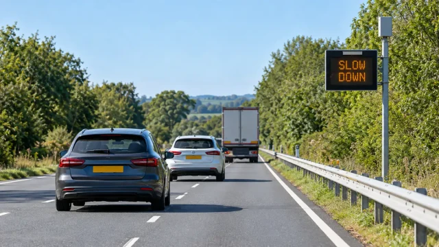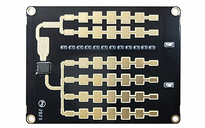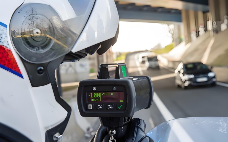

A speed radar camera combines vehicle speed measurement with image capture and evidence processing. The radar measures vehicle movement, while the camera records the vehicle and, where required, its registration plate. A controller then associates the correct radar target with the correct image and creates a reviewable event record.
This combination is used in fixed, mobile and multi-lane speed enforcement systems. However, installing a radar beside a camera does not automatically create a reliable enforcement system. Measurement geometry, target association, time synchronization, image quality, system verification and local legal requirements must all be addressed together.
What Is a Speed Radar Camera?
The term “speed radar camera” usually refers to a system rather than a single sensor. A typical system may include:
- A radar sensor for measuring vehicle speed and position
- One or more overview or license-plate cameras
- Illumination for nighttime image capture
- A controller or edge-processing unit
- Time synchronization and event association software
- Local storage or a network connection
- Monitoring, review and evidence-management software
The radar and camera perform different jobs. Radar provides measurement data; the camera provides visual identification and context. The controller must determine which vehicle produced the measured speed and which images belong to that event.
How Speed Radar Measurement Works
Traffic speed radar transmits radio-frequency energy toward the road. A moving vehicle reflects part of this energy back to the radar. Relative motion changes the frequency of the returned signal, producing a Doppler shift.
The larger the relative speed between the radar and the vehicle, the larger the frequency shift. Radar processing uses this change to estimate the vehicle’s radial speed relative to the sensor.
More advanced traffic radars may also estimate:
- Distance from the radar
- Lateral position
- Travel direction
- Lane assignment
- Continuous target trajectory
- Measurement-line crossing time
These additional outputs are particularly important in multi-lane camera systems because speed alone may not identify which vehicle should be photographed.
The importance of measurement angle
A conventional Doppler radar measures the component of vehicle speed directed along the radar beam. If the radar observes the vehicle at an angle, the measured radial speed may differ from the vehicle’s actual direction-of-travel speed. This relationship is commonly described as the cosine effect.
The correct installation geometry depends on the radar design, tracking method and approved system configuration. There is no universal mounting angle that is correct for every speed radar camera. Installation should follow the manufacturer’s instructions and any applicable approval or regulatory requirements.
How the Camera and Radar Work Together
The central challenge is not simply measuring speed or taking a photograph. It is associating the measurement with the correct vehicle.
A typical event sequence is:
- The radar detects and begins tracking a vehicle.
- The system calculates the vehicle’s speed and position.
- The target enters or crosses a defined measurement area.
- The controller sends a trigger or associates a time-stamped camera frame.
- The camera captures one or more images.
- The controller links the target data, images and system information.
- The event is stored for automatic or manual review.
In light traffic, basic triggering may appear sufficient. In dense multi-lane traffic, reliable association requires position, direction, lane and timing information so that nearby vehicles are not confused.
What Should an Evidence Record Contain?
Required evidence varies by country and jurisdiction. Depending on the applicable rules and approved system design, a speed enforcement record may include:
- Measured vehicle speed
- Applicable speed limit
- Date and time
- Location or enforcement-site identifier
- Vehicle image and registration-plate image
- Lane or travel direction
- Measurement position or reference line
- Device or system identifier
- System status and verification information
- Additional image or secondary-check information
The evidence format should be defined before integration begins. A system integrator should not assume that a speed value and a single vehicle image will satisfy every legal or operational requirement.
Primary and Secondary Speed Checks
Some automated enforcement frameworks require an independent secondary method that allows the primary speed measurement to be checked. The exact requirement depends on local law, system type approval and enforcement procedure.
A secondary check may use road markings, two images taken at a defined interval, independently derived position data or another approved method. The United Kingdom’s enforcement camera handbook, for example, specifies requirements for an independent secondary speed check in relevant automatic systems.
This should not be treated as a universal rule for every country. Before deployment, the supplier and integrator should confirm:
- Whether formal device or system approval is required
- Whether an independent secondary check is required
- Which evidence fields must be retained
- How verification and calibration records must be managed
- Whether events require manual review
- How data protection and retention rules apply
Fixed, Mobile and Multi-Lane Systems
Fixed speed radar cameras
A fixed system is installed at a defined roadside or overhead location. Because the geometry remains stable, the detection area, measurement zone and camera view can be configured for that site. Fixed systems still require periodic inspection and verification according to the applicable operating procedure.
Mobile speed camera systems
Mobile systems may be installed in enforcement vehicles, trailers or portable roadside equipment. Their flexibility introduces additional setup requirements. Position, aiming, stability, site suitability and pre-operation checks must be controlled for each deployment.
Multi-lane radar camera systems
A multi-lane system must separate vehicles travelling in adjacent lanes and may also need to handle vehicles moving in different directions. A suitable radar may output target coordinates, speed and trajectories rather than a single speed value.
The integration should be tested with:
- Vehicles travelling side by side
- Large vehicles obscuring smaller vehicles
- Lane changes near the measurement zone
- Closely spaced vehicles
- Different vehicle sizes and speeds
- Vehicles entering or leaving the radar coverage area
Speed Radar Camera Versus Radar Speed Gun
A radar speed gun is normally used by a trained operator to measure the speed of a selected vehicle. The operator observes the traffic environment, identifies the target and develops the required tracking history.
An automated speed radar camera must perform more of this process through sensors and software. It must detect targets, determine which vehicle is being measured, trigger or select the correct image and preserve the event data.
| Characteristic | Radar speed gun | Automated radar camera |
|---|---|---|
| Target selection | Primarily performed by the operator | Performed by tracking and association logic |
| Image capture | Not always included | Integrated into the event workflow |
| Operating mode | Manual or operator-assisted | Fixed, mobile or automated |
| Evidence creation | Depends on operator procedure | Generated as a synchronized event record |
| Multi-lane association | Relies heavily on operator observation | May use target position and trajectory |
For a detailed explanation of handheld and vehicle-mounted speed radar, read Radar Speed Guns: How They Work and Measure Vehicle Speed.
Site Survey and Installation Planning
Before equipment is selected, the integrator should inspect the proposed site and document:
- Number and width of lanes
- Traffic direction
- Road curvature and gradient
- Available mounting structures
- Distance between the radar, camera and measurement zone
- Possible obstruction by barriers, signs or vegetation
- Expected vehicle density and vehicle types
- Power, grounding and lightning-protection requirements
- Network connection and data-storage requirements
- Camera lighting conditions during the day and at night
- Safe access for installation and maintenance
There is no universal requirement for mounting every system at the same height or angle. The radar coverage area and camera view must be designed together for the selected equipment and site.
Time Synchronization and Coordinate Alignment
Radar and camera data must refer to the same event. Even when both devices are connected to the same controller, differences in device clocks, network latency, camera exposure timing and processing delay can cause incorrect association.
The integration specification should define:
- The time source used by every device
- Time-stamp precision and format
- Maximum permitted timing difference
- Trigger and acknowledgement behaviour
- Radar-to-camera processing delay
- Behaviour after a restart or communication interruption
If target coordinates are used, the radar coordinate system must also be mapped to the road and camera view. The origin, axis direction, units, lane boundaries and measurement line should be documented.
Verification, Calibration and Functional Testing
Calibration, verification and routine function tests are related but not identical.
- Calibration establishes or confirms measurement performance against a traceable reference where required.
- Verification checks that the system continues to meet defined performance or approval requirements.
- Functional testing confirms that the radar, camera, illumination, communication and event-processing functions operate correctly.
The required schedule must come from the device documentation, system approval conditions and local enforcement rules. A generic quarterly or annual interval should not be applied to every installation without supporting requirements.
A commissioning test should include more than a single passing vehicle. Test cases should cover:
- Different lanes and directions
- Multiple simultaneous vehicles
- Slow and fast vehicles within the intended operating range
- Large and small vehicles
- Daytime and nighttime images
- Plate readability where applicable
- Communication loss and system recovery
- Event record completeness
- Correct association between speed and image
Common Integration Problems
Correct speed, wrong vehicle image
This normally indicates an association problem rather than a basic radar measurement problem. Review timing, lane assignment, target coordinates, camera coverage and trigger delay.
Unstable target tracking
Possible causes include poor installation geometry, obstruction, excessive mounting vibration, strong reflections or unsuitable tracking configuration.
Duplicate or missing events
Check the measurement-zone definition, target creation and deletion logic, trigger hold time, communication retries and controller event-handling rules.
Clear daytime images but poor nighttime evidence
Review illumination, exposure time, camera angle, plate reflection, vehicle speed and synchronization between the trigger and camera exposure.
Incorrect lane assignment
Verify the radar coordinate mapping, configured lane boundaries and mounting position. Physical lane geometry should be measured rather than estimated from an image alone.
Choosing Radar for Camera Integration
For a basic single-lane trigger, a simple speed output may be sufficient. More complex systems may require individual target coordinates and continuous tracking.
When selecting radar, ask:
- How many lanes and travel directions must be covered?
- Does the camera need a trigger or continuous target data?
- Must the system distinguish simultaneous vehicles?
- Is lane assignment required?
- What output rate and latency can the controller accept?
- Which physical and network interfaces are supported?
- How are target IDs created and removed?
- How will the radar data be verified against images?
- What approval requirements apply to the complete system?
The HC-M150 multi-lane traffic radar provides target-level measurements for system integration. Whether it is suitable for a particular enforcement project depends on the required detection area, system architecture, validation process and applicable certification requirements.
For an overview of the complete workflow, visit our speed enforcement integration solution.
Frequently Asked Questions
Does the camera measure vehicle speed?
In a radar-camera system, the radar normally provides the speed measurement. The camera records visual evidence. Other types of camera systems may calculate speed using different approved methods.
Can one radar camera monitor several lanes?
Some systems are designed for multiple lanes, but the capability depends on the radar, mounting geometry, traffic conditions, camera coverage and target-association method. Multi-lane performance should be validated at the intended site.
Can a speed radar camera identify the wrong vehicle?
Incorrect association is possible if the system is poorly designed or configured. Target position, lane data, synchronized timing, trajectories and secondary verification help reduce this risk.
Do all speed radar cameras require calibration?
Requirements differ by device and jurisdiction. Follow the manufacturer’s documentation, system approval conditions and local enforcement procedure rather than applying a universal schedule.
Do radar cameras work at night?
Radar measurement does not depend on visible light, but the camera still requires suitable exposure and illumination to produce usable images. Nighttime radar and nighttime imaging should therefore be tested separately.
Is every traffic radar suitable for issuing citations?
No. A sensor may provide useful speed and target data without being approved as part of an enforcement system. Legal use depends on the complete system, its evidence process and the requirements of the relevant jurisdiction.
Conclusion
A reliable speed radar camera system must do three things correctly: measure vehicle speed, associate the measurement with the correct vehicle and create a complete evidence record. Radar performance alone is not enough.
System integrators should evaluate site geometry, target tracking, camera timing, image quality, communication, verification and legal requirements as one coordinated design. This approach produces a more dependable system than treating the radar, camera and software as separate components.