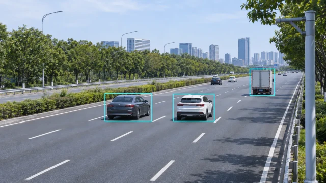
Radar cameras combine radar measurement with visual imaging. Radar detects and tracks vehicles or other road users, while cameras provide images or video that help operators understand what is happening on the road.
The value of the system comes from connecting these two data sources correctly. A camera image without target data may require continuous video analysis, while radar data without an image may not provide enough visual context. When time, position and target information are aligned, radar and video can support traffic monitoring, event detection, speed measurement and system control.
This guide focuses on infrastructure-mounted radar camera systems used beside or above roads. It explains the roles of the radar and camera, the main integration methods and the technical issues that system integrators should address.
What Is a Radar Camera System?
A radar camera system normally consists of separate sensing and processing components rather than one universal device. A typical installation may include:
- A radar sensor that detects and tracks targets
- One or more overview or license-plate cameras
- An edge controller or industrial computer
- Time-synchronization services
- Radar-to-camera association software
- A traffic management, monitoring or evidence platform
- Power, network and environmental protection equipment
The radar may provide speed, range, lateral position, direction, lane assignment and trajectory. The camera supplies visual information such as vehicle appearance, traffic conditions, road obstruction and scene context.
Not every installation requires all of these outputs. A simple system may use radar only to trigger image capture. A more advanced system may continuously project radar targets onto live video and associate each tracked vehicle with image data.
What Radar and Cameras Each Contribute
| Function | Radar contribution | Camera contribution |
|---|---|---|
| Vehicle detection | Detects reflected radio-frequency signals | Detects or confirms objects in the image |
| Speed measurement | Measures radial speed and may estimate a velocity vector | May provide a visual or secondary reference |
| Position | Provides range and lateral position when supported | Provides position in image coordinates |
| Continuous tracking | Maintains target tracks and trajectories | Maintains visual tracks when image processing is used |
| Vehicle appearance | Usually limited | Provides color, shape, plate image and scene context |
| Operation in darkness | Measurement does not depend on visible illumination | Requires suitable imaging and possibly illumination |
| Event review | Provides measured data | Provides visual evidence or operator context |
Radar and cameras should therefore be treated as complementary sensors. One does not automatically remove the limitations of the other.
Two Main Radar-Camera Integration Methods
1. Radar-triggered image capture
In a trigger-based system, radar detects a defined event and instructs the camera or controller to capture an image. Typical triggers include:
- A vehicle entering a detection zone
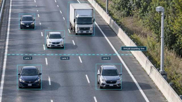
- A target crossing a virtual line
- A measured speed exceeding a threshold
- A vehicle stopping in a monitored area
- A vehicle travelling in an unexpected direction
This approach can reduce unnecessary image processing and network traffic. However, the trigger must still be associated with the correct vehicle, especially when several vehicles enter the monitored area at nearly the same time.
2. Continuous radar-video association
In continuous association, the radar outputs target tracks repeatedly while video is streamed or processed. Software maps the radar coordinates into the camera view and attempts to maintain a relationship between each radar track and the corresponding image object.
This method can support:
- Vehicle labels overlaid on live video
- Speed and lane data displayed for individual vehicles
- Traffic-event verification
- Stopped-vehicle or wrong-way alerts
- Automatic selection of a camera region of interest
- Search and playback using radar target data
Continuous fusion provides more information than a simple trigger, but it also requires accurate synchronization, coordinate calibration and track-management logic.
Target-to-Image Association
The most important integration task is determining which image object corresponds to which radar target.
Association may use a combination of:
- Target time stamps
- Radar position and trajectory
- Configured lane boundaries
- Direction of movement
- Camera image position
- Visual tracking results
- Expected travel time between detection and image zones
A system that works with one isolated vehicle may fail in dense traffic. Validation should therefore include vehicles travelling side by side, lane changes, overtaking, large trucks and closely spaced targets.
Temporary target identifiers
A radar target ID is normally a temporary tracking reference, not a permanent identity assigned to a vehicle. The system should define what happens when a target is first detected, temporarily obscured, split into multiple tracks or removed from the radar’s field of view.
The camera platform should not assume that the same target ID will remain valid indefinitely or survive a device restart.
Coordinate Mapping Between Radar and Camera
Radar and cameras describe position differently. A radar may report target coordinates in metres relative to the sensor, while a camera reports image positions in pixels. These coordinate systems must be mapped if radar targets are to be displayed or matched accurately in the image.
The integration should document:
- The radar coordinate origin
- The direction of the longitudinal and lateral axes
- Measurement units
- Radar mounting position and orientation
- Camera position, angle and lens characteristics
- Road-plane reference points
- Lane boundaries and monitored zones
Calibration normally uses known points or reference positions visible to the camera and measurable within the radar coordinate system. The method must also account for changes caused by camera zoom, camera movement, pole vibration or maintenance work.
Time Synchronization and Latency
Even accurate coordinates cannot produce reliable association if radar and camera records use different times.
Timing errors may come from:
- Unsynchronized device clocks
- Network transmission delay
- Camera exposure and encoding delay
- Radar tracking and filtering delay
- Controller processing time
- Buffered video streams
The system specification should identify the common time source, time-stamp format, expected precision and maximum acceptable delay. It should also define how devices recover synchronization after a restart or network interruption.
For trigger-based capture, integrators should measure the complete delay from the radar event to the actual camera exposure rather than considering only the network transmission time.
Traffic Monitoring Applications
Traffic flow monitoring
Radar can provide vehicle trajectories, speed and lane-level measurements, while cameras allow operators to confirm traffic conditions visually. Depending on the radar and processing platform, the system may calculate:
- Traffic volume
- Average speed
- Lane occupancy
- Vehicle headway
- Queue development
- Travel direction
The image should be treated as a source of context rather than automatically assumed to be the measurement reference. Statistical definitions and aggregation intervals should be documented.
See our traffic flow monitoring solution for an overview of target-level radar data and traffic statistics.
Stopped-vehicle and incident detection
A tracking radar may detect a target that slows or stops inside a defined zone. The system can then direct the operator to the relevant camera image or save a short video clip for review.
Potential applications include:
- Stopped vehicles on highways
- Vehicles travelling in the wrong direction
- Unexpected queues
- Objects occupying a restricted road area
- Vehicles entering a closed or controlled lane
Event thresholds should be designed for the road environment. A stopped target at an intersection is normal, while the same condition in a high-speed lane may require an alert.
Intersection monitoring and signal control
Radar may provide lane presence, approach speed and queue information to a traffic controller. Cameras can support remote observation and operational verification.
If radar data is used directly for signal control, the failure mode must be defined. The controller should know how to respond when radar data becomes unavailable, delayed or invalid.
Speed measurement and enforcement integration
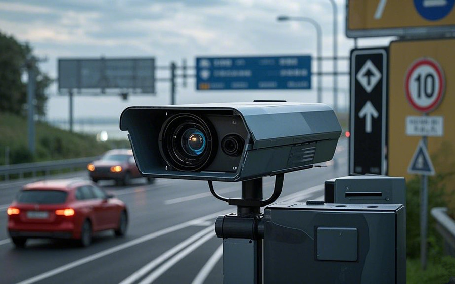
Radar-camera systems can also associate measured vehicle speed with an image. Enforcement use requires additional attention to system approval, measurement verification, evidence records and local legal requirements.
For this specific application, read Speed Radar Cameras: How Automated Enforcement Systems Work and our speed enforcement integration solution.
Radar Camera Versus a Standalone Traffic Camera
A camera can support vehicle detection and classification through video analytics. Radar adds an independent measurement source that does not require visible illumination to detect target motion.
However, radar should not be described as unaffected by every environmental condition, and the camera still has its own visibility and lighting requirements. The performance of the combined system depends on:
- Radar coverage and target separation
- Camera field of view and image resolution
- Lighting and visibility
- Mounting stability
- Road geometry
- Occlusion by large vehicles
- Calibration and synchronization
- Fusion and event-processing software
The Federal Highway Administration identifies microwave radar sensors, video image processors and combined sensor technologies as options for roadway traffic detection. Selection should be based on the required traffic data and the characteristics of the deployment site.
Site Survey and Installation Planning
The site survey should examine both radar coverage and camera visibility. Important questions include:
- Which lanes and travel directions must be monitored?
- Where are the required detection and image zones?
- Can large vehicles obstruct other targets?
- Are there barriers, signs, trees or structures in the sensor view?
- Does the road curve, rise or fall within the monitored area?
- Are the available poles or gantries sufficiently stable?
- Is suitable power, grounding and surge protection available?
- How will radar data and video be transmitted?
- Can equipment be accessed safely for maintenance?
- Will the camera produce usable images at night?
FHWA guidance notes that the footprint of an over-roadway sensor depends on mounting height, offset, sensor aperture, road geometry and possible obstructions. A configuration from one road should not be copied to another without a site-specific review.
Commissioning and Validation
A radar camera system should be validated as an integrated system. Testing the radar and camera separately is necessary, but it does not prove that their outputs are associated correctly.
A commissioning plan should include:
- Single vehicles in each monitored lane
- Vehicles travelling side by side
- Closely spaced traffic
- Lane-changing vehicles
- Passenger cars, motorcycles and large vehicles
- Low-speed and stopped targets where relevant
- Daytime and nighttime images
- Communication interruption and recovery
- Device restart and time resynchronization
- Verification of event records and target-image association
Acceptance criteria should be defined before testing. Detection rate, speed error, lane assignment, track continuity, event latency and image quality are different performance measures and should be evaluated separately.
Common Radar Camera Integration Problems
Radar target does not align with the image
Check the coordinate transformation, radar orientation, camera angle, road reference points and whether the camera has moved since calibration.
The correct event has the wrong vehicle image
Review time synchronization, camera exposure delay, lane mapping, target association and behaviour when several vehicles cross the trigger area together.
Labels move away from vehicles in the video
This may be caused by incorrect perspective mapping, video latency, unstable mounting or a mismatch between radar and camera update timing.
Targets disappear behind trucks
Review sensor mounting position and the effect of occlusion. A higher or more central installation may improve visibility, but the final geometry must follow product guidance and site constraints.
Too many false event alerts
Check detection-zone boundaries, minimum event duration, traffic behaviour, reflections from roadside structures and whether the event rule is suitable for that location.
Data, Privacy and Cybersecurity
Radar measurements may contain limited identifying information, but camera images can contain registration plates, vehicle details and people. The complete system should therefore define:
- Which images and target data are stored
- How long records are retained
- Who can view or export them
- How records are encrypted and transferred
- How user access and system changes are logged
- How software and device credentials are maintained
Data handling should follow the privacy, cybersecurity and evidentiary requirements applicable to the deployment location.
How to Select Radar for Camera Integration
Before selecting a radar, define what the camera system needs from it:
- Is a simple trigger sufficient, or are continuous target tracks required?
- How many lanes and directions must be covered?
- Does the system require speed, range, lateral position or trajectory?
- Must slow or stationary vehicles be detected?
- What output rate and latency can the controller accept?
- Which communication interface and protocol are required?
- How will radar coordinates be mapped into the camera view?
- How will field performance be validated?
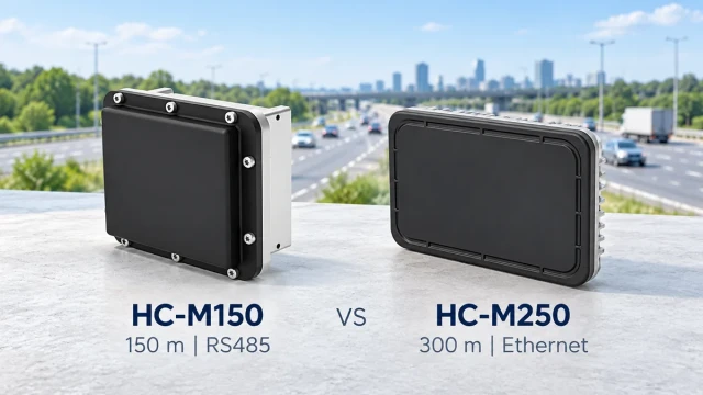
The HC-M150 multi-lane traffic radar provides target-level speed and position data for traffic system integration. Suitability depends on the required coverage, road geometry, controller interface and validation criteria.
For more detail about roadside detection requirements, see Radar Sensor for Vehicle Detection: A Practical Roadside Guide.
Frequently Asked Questions
Is a radar camera one device?
It may be sold as an integrated unit, but many systems use separate radar, camera and controller components. The important issue is how their measurements, time stamps and coordinates are connected.
Can radar identify a license plate?
Radar does not read a license plate. It detects and measures targets. A suitable camera and image-processing system are required to capture or recognise a plate.
Can radar cameras operate at night?
Radar measurement does not require visible illumination, but the camera still needs appropriate imaging settings and possibly infrared or visible illumination. Nighttime image performance must be tested separately.
Can a radar camera monitor multiple lanes?
Some radar camera systems are designed for multiple lanes. Actual performance depends on radar capability, mounting geometry, target occlusion, camera coverage and association software.
Does radar always perform correctly in rain and fog?
Radar does not depend on visible light in the same way as a camera, but no sensor should be described as unaffected by every environmental condition. System performance should be tested against the project’s weather and visibility requirements.
Is a radar camera automatically suitable for enforcement?
No. A traffic monitoring system may measure speed and capture images without meeting the approval, verification and evidence requirements for legal enforcement. These requirements depend on the complete system and jurisdiction.
Conclusion
Radar cameras combine measurement with visual context. Radar can provide target speed, position and trajectory, while cameras provide images that operators and software can interpret.
The quality of the combined system depends on target association, coordinate mapping, synchronization and site-specific validation. System integrators should define these requirements before selecting hardware and should test the radar, camera and software together under realistic traffic conditions.