To test traffic radar vehicle counting accuracy, compare radar counts with a reviewed video reference at the same counting line, in the same direction and over the same time window. Check each lane separately, then investigate missed passages, extra counts and incorrect lane assignments. A total count that matches the reference is not enough to establish reliable performance.
This guide explains a practical commissioning workflow for multi-target roadside radar. The numerical examples are illustrative, not measured results for HC-M150, HC-M250 or any customer installation.
1. Define exactly what counts as one vehicle passage
Write down the counting rule before recording the test. A vehicle passing through a radar’s observation area is not necessarily a counted passage: the relevant event is crossing the configured counting line under the selected direction and lane rules.
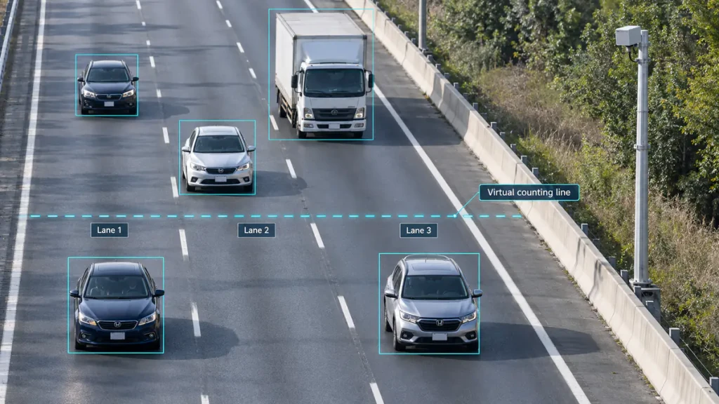
- Location: identify the exact virtual counting line and its corresponding position in the reference video.
- Direction: specify approaching, departing or separately reported directions.
- Lane: assign lane numbers using a saved road sketch, not an assumption about left-to-right numbering.
- Vehicle scope: state whether motorcycles and other road users are included, excluded or evaluated separately.
- Time window: define start and end times and how boundary events are assigned. For example, include passages at or after the start and before the end.
- Special movements: document how the configured system handles lane changes, reversing and repeated crossings during stop-and-go traffic.
Use the same passage reference point, such as the vehicle front, where the radar’s event definition supports that comparison. If the system reports a tracked reference point instead, understand its timing relationship before deciding that a video passage and a radar event do not match.
For definitions of volume, occupancy and headway, see the traffic flow measurement guide. This test concerns passage counts; it does not independently validate speed, classification or occupancy accuracy.
2. Record a usable video reference and synchronise the data
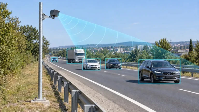
Choose a camera position that clearly shows the counting line and every lane being evaluated. Avoid a view in which a nearby truck repeatedly hides the far lane. An unclear reference cannot establish that the radar is wrong.
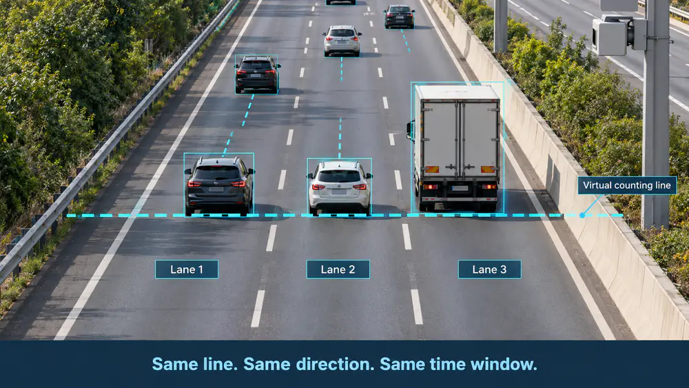
Conceptual example: compare the same counting position, direction, lanes and time window; the overlay is not an actual radar-software screen.
Record the original video, radar output and collection timestamps. Check clock offsets and whether timestamps describe measurement time, message transmission or arrival at the host. A known offset can be corrected in the comparison; variable network delay requires more careful event alignment.
Review the recording and log each reference passage by lane and time. Replay uncertain events and, where practical, have another reviewer check disputed passages. Flag unresolved intervals explicitly instead of silently treating them as a perfect reference or dropping them to improve the result.
Start with a short pilot recording to verify visibility and timing. Then collect the agreed acceptance sample across representative traffic conditions. Neither a brief successful clip nor an arbitrarily chosen vehicle count proves performance across an entire site.
3. Compare counts lane by lane before looking at the total
For a valid reference count greater than zero, use these two clearly labelled measures:
- Signed count error (%) = (radar count − reference count) / reference count × 100. A negative value indicates a net undercount; a positive value indicates a net overcount.
- Absolute count error (%) = |radar count − reference count| / reference count × 100. This describes the size of the count difference, not the percentage of individual passages correctly detected.
Illustrative example only: these are invented counts for explaining the calculation, not product performance data.
| Lane | Reviewed reference | Radar count | Signed count error |
|---|---|---|---|
| Lane 1 | 200 | 190 | −5.00% |
| Lane 2 | 180 | 190 | +5.56% |
| Lane 3 | 120 | 120 | 0.00% |
| All lanes | 500 | 500 | 0.00% |
The overall count matches, but two lanes do not. Incorrect lane assignment is one possible explanation; separate undercounting and overcounting are another. The totals alone cannot distinguish them.
Report each lane and interval rather than averaging percentages without considering sample sizes. If a combined absolute-error measure is required, define its weighting explicitly. When the reference count is zero, the percentage formulas are undefined: report zero reference vehicles and the number of extra radar counts instead.
4. Check individual passages for missed, extra and wrong-lane counts
Where passage-level records are available, match each reference passage to at most one radar passage using an agreed time tolerance, direction and supporting evidence. Keep unmatched records for investigation. A raw target update is not automatically a passage event, and a track ID should not be assumed to remain unique across the whole recording.
A second illustrative example: the video contains 500 passages. Of these, 490 are matched and 10 are missed. The radar also reports 10 extra counts. Its total is still 500, producing zero net count error despite the event-level problems.
- Missed-reference rate: 10 / 500 × 100 = 2%.
- Extra-count proportion: 10 / 500 radar counts × 100 = 2%.
- Matched-reference proportion: 490 / 500 × 100 = 98%.
These are different measures. Do not present them as one interchangeable “accuracy” number or as a statistically established product specification. A wrong-lane passage may still match at the road level; mark its lane assignment separately. Extra counts can include duplicates, out-of-scope objects or other unmatched events, so investigate before assigning a cause.
If only interval totals are available, you can compare volume bias, but you cannot reliably separate missed and duplicate passages. Arrange a supported event-recording method with the supplier or state that limitation in the report.
5. Investigate the pattern before changing settings
| Observed pattern | Check first | Next step |
|---|---|---|
| One lane is low and an adjacent lane is high | Lane mapping and movements near the counting line | Review matched passages before changing lane boundaries |
| Far-lane losses occur behind large vehicles | Occlusion in both the radar view and the reference video | Review installation geometry and obtain a clear reference |
| Counts increase during queue movement or reversing | Direction and repeated-crossing rules | Check whether the observed sequence follows the configured policy |
| Adjacent intervals differ but a longer total agrees | Clock offsets, interval boundaries and reporting delay | Align passage times and bin definitions before retesting |
| Counts disappear during connection interruptions | Host logs, missing reports and restart handling | Separate data loss from sensing loss; do not replace missing data with zero |
| Host totals rise when reports are repeated | Whether messages are cumulative totals, interval totals or repeated states | Correct accumulation and duplicate handling in the receiving application |
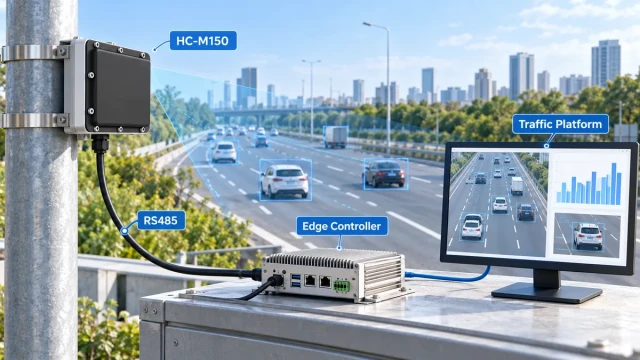
These patterns suggest checks, not confirmed diagnoses. Preserve the previous configuration, change one relevant item and record the reason. Refer to the HC-M150 installation guide for mounting and lane setup, or the RS485 integration guide for distinguishing target updates from traffic statistics.
6. Retest under the conditions the project actually needs
After an adjustment, use a fresh sample and repeat the same reference method. Check both the original problem condition and the lanes or movements that already worked. A correction in one lane must not simply move the error into another.
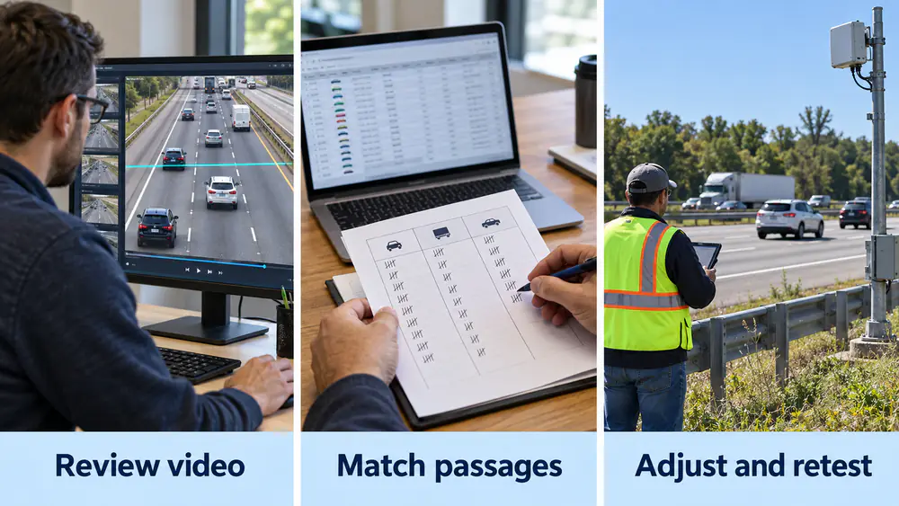
Review the reference video, match passage records where available, and retest after changing one relevant setting.
Include the conditions relevant to the deployment: free-flow and queued traffic, large vehicles beside smaller vehicles, lane changes near the counting line, different lighting and weather, and all required lanes and directions. Record conditions not tested and any gaps in the reference.
Agree the acceptance limits, sample coverage and treatment of unavailable data before the final test. There is no universal counting threshold or test duration in this article. Passing a count test also does not certify a system for speed enforcement.
Report end-to-end data availability separately. Accurate counts during connected periods do not establish that a daily report is complete when several intervals were lost.
7. Keep a repeatable commissioning record
Use the following as a record structure, not a pre-filled acceptance certificate:
| Record item | What to retain |
|---|---|
| Site and configuration | Device model, firmware, mounting geometry, lane sketch, counting line and configuration revision |
| Reference and timing | Video file, visible line position, reviewer, clock offset, event-matching rule and interval boundaries |
| Sample coverage | Start/end, valid duration, lane/direction, reference count, traffic state, weather and excluded or unresolved intervals |
| Results | Radar count, signed/absolute count error, missed/extra events and wrong-lane assignments where observable |
| System availability | Missing reports, connection interruptions, restarts and their treatment in the final totals |
| Change and decision | Previous/new setting, retest result, agreed criterion, remaining limitations and reviewer approval |
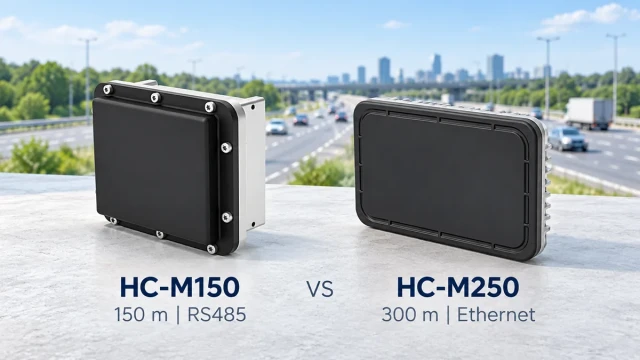
When evaluating HC-M150 or HC-M250, identify the supported output and its counting definition before choosing a validation method. Match the interface and configuration to the device documentation; this guide does not imply identical event logging or settings across models.
For a traffic flow monitoring project, prepare a road sketch, required lanes and directions, intended counting position, available host interface and acceptance requirements before requesting support. Share sensitive recordings privately through the agreed support channel.
The practical conclusion: use the same counting rule, validate each lane, investigate individual mismatches where the data allows, and retest after changes. A matching total is the beginning of verification, not its conclusion.
Technical reference
The FHWA Traffic Monitoring Guide, Chapter 2 discusses manual observations as a way to verify automated detection equipment. The workflow, example calculations and record structure above are practical guidance for this article, not a quoted FHWA certification procedure or an endorsement of any product.