The HC-M150 multi-target traffic radar supports installation heights from 1 to 10 metres. For fixed traffic counting and speeding camera applications, 4–6 metres on an overhead crossbar is the recommended starting point. For roadside portable speed measurement, installation at approximately 1 metre is also possible, although the usable detection range becomes shorter and distant vehicles are more likely to be obscured.
The radar can be installed above the road, beside the road on a streetlight or dedicated pole, or at a suitable position near the road centre. After mounting, configure the installation height, horizontal angle and elevation angle in the setup software, then define the lanes and measurement lines.
This guide explains how to choose an installation position and commission the HC-M150 multi-target traffic radar for a working traffic monitoring or speed measurement system.
1. Choose the installation height for the application
Installation height should follow the job the radar needs to perform.
| Installation height | Typical application | Practical considerations |
|---|---|---|
| Approximately 1 m | Roadside portable or mobile speed measurement | Suitable for a local measurement area. Expect shorter usable coverage and more obstruction of distant targets. |
| 4–6 m | Overhead traffic counting and speeding camera integration | Recommended standard arrangement for detection coverage and tracking performance. |
| Above 6 m, up to 10 m | Sites with higher mounting structures | Supported, but the elevation angle and actual lane coverage must be checked at the installed height. |
Use 4–6 metres for a standard fixed installation
For a new fixed installation with an available overhead crossbar, start with a mounting height of 4–6 metres.
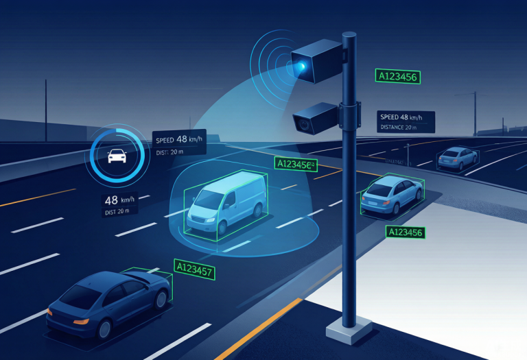
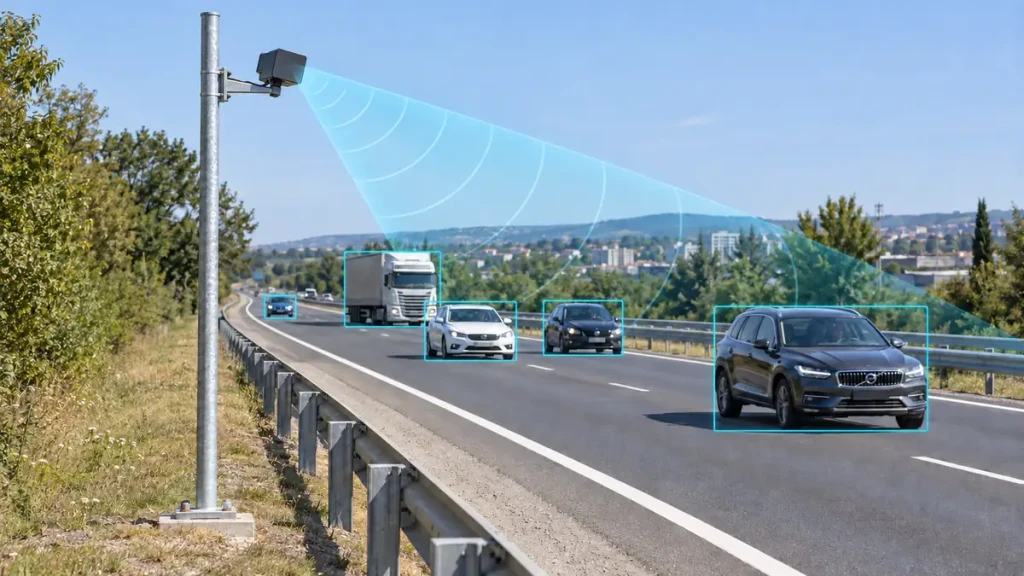
This arrangement is suitable for traffic flow statistics and radar-assisted speeding camera systems. The elevated position helps the radar observe vehicles further along the road and reduces the obstruction that occurs with low roadside mounting.
The HC-M150 has a nominal detection range of 150 metres. This does not mean every mounting position will provide an unobstructed 150-metre view. The installation geometry and vehicles between the radar and distant targets affect usable coverage.
For a traffic flow monitoring system, check the full lane area used for counting. For speed enforcement integration, check tracking and target association around the selected measurement line.
Use approximately 1 metre for portable roadside speed measurement
A mounting height of approximately 1 metre can be used when integrating HC-M150 into a roadside portable speed measurement unit.
At this height, nearby vehicles can obstruct vehicles further away, especially when larger vehicles pass through the field of view. The usable detection area will therefore be smaller than in a typical overhead installation.
This arrangement can still meet the needs of a portable speed meter when the required measurement area is local and clearly visible. Position the unit to obtain a clear view of that area rather than attempting to reproduce the coverage of a high-mounted traffic monitoring installation.
Higher mounting is possible
HC-M150 can also be installed above the standard 4–6-metre height, within its 1–10-metre installation range.
If an existing structure requires a higher position, enter the actual height in the alignment settings and adjust the radar elevation to cover the required road section. Higher mounting is an available option, but it should not be treated as an automatic improvement over the recommended standard arrangement.
2. Choose an overhead, roadside or road-centre position
HC-M150 installation does not require one fixed mounting location.
Overhead crossbar mounting
An overhead crossbar is the recommended arrangement when planning a standard fixed installation. Choose a position with a clear view of the monitored lanes and sufficient adjustment for horizontal aiming and downward tilt.
Avoid placing the radar behind signs, structural members or other equipment that blocks its view of the road.
Roadside pole mounting
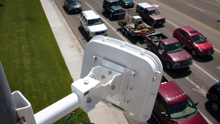
The radar can be installed on a streetlight pole or an ordinary dedicated pole beside the road.
Aim the radar towards the required detection area, then enter the actual mounting geometry in the alignment settings. Roadside installation is useful where an overhead crossbar is unavailable, but the view across the lanes should be checked with live traffic.
In particular, observe whether vehicles in the nearer lanes obscure vehicles in the further lanes. If they do, changing the mounting position or height may be more effective than changing the software settings alone.
Road-centre mounting
A suitable mounting position near the road centre is also possible. Adjust the radar’s horizontal angle to face the required detection area and configure the corresponding azimuth in the software.
The important point is that the software settings must represent the actual radar orientation. A flexible mounting position still requires accurate alignment.
3. Set the horizontal and vertical aiming angles
Start by pointing the radar towards the road area you want to monitor.
The horizontal angle, also called azimuth, determines the direction the radar faces across the road. Adjust it for the selected overhead, roadside or road-centre position.
The vertical angle, or elevation, determines how far up or down the road the radar is aimed. The HC-M150 user manual provides these adjustment references:
- For a shorter detection area: approximately −10° to −6°.
- For a longer detection area: approximately −2° to 0°.
Use these as starting ranges, then check the required road section in the live target display. They are not a guarantee of a particular detection distance at every installation height.
For example, an overhead installation intended to observe traffic further along the road should begin with the long-distance angle reference. A low-mounted portable speed meter should be aimed at its local measurement area rather than configured solely to maximise distant coverage.
After changing the physical mounting angle, update the alignment settings to match. Do not leave the software using the previous angle.
4. Connect power and RS485 communication
The supplied HC-M150 manual specifies a 12 V DC power supply, with a current of approximately 300–400 mA.
Its connector assignments are:
| Pin | Function | Wire colour |
|---|---|---|
| 1 | Sensor VCC, +12 V | Red |
| 2 | Sensor GND | Black |
| 3 | RS485 B | Blue |
| 4 | RS485 A | Brown |
Check the connector supplied with your unit against its accompanying documentation before wiring. Keep the power connection separate from the RS485 signal connections.
In the setup software, select the communication port and click Start. Establish communication before configuring the installation geometry.
5. Enter the actual mounting geometry in Alignment
Open Alignment and configure:
- Altitude: the actual installation height.
- Azimuth: the horizontal mounting angle.
- Elevation: the vertical mounting angle.
Enter these values as accurately as possible. The manual specifically notes that inaccurate alignment values affect accuracy.
Click Send to Sensor after configuring the parameters.
Then observe vehicles travelling through the monitored area. Check whether the displayed tracks follow the expected road direction. If tracks appear rotated relative to the road, recheck the horizontal aiming and azimuth value before changing the lane boundaries.
The correct sequence is to establish the mounting geometry first, then configure the lanes around the aligned target display.
6. Configure the lanes and measurement lines
Define the lanes
Open Lanes and configure the number, width and length of the lanes to be detected.
Use the actual lane layout. Check vehicles in each lane to confirm that the configured boundaries correspond to their displayed positions.
Click Send to Sensor after making changes.
Define the measurement lines
Open MeasLines to configure the number and distance of the measurement lines. The manual supports up to four measurement lines and states that cyclic statistics are based on the measurement-line position.
Place each line within an area where the required vehicles can be observed reliably.
For traffic counting, check vehicle passage at the selected line. For a radar-assisted camera system, verify the relationship between the radar measurement line and the camera’s working area.
A measurement line in the radar software does not, by itself, complete camera integration. The controller and camera workflow must also be tested with the radar data.
7. Set the detection area and statistics interval
Open Area to configure the detection area and target speed range.
Limit the area to the road section needed by the application. The manual notes that narrowing the detection range can reduce data processing.
The software also allows direction filtering through the speed range. In the supplied manual, −300 to 0 km/h is given as an example for detecting approaching vehicles while excluding departing vehicles. Confirm the displayed speed sign with live traffic before applying this filter.
Open Statistics to set the traffic flow collection interval. The documented range is 1–3,600 seconds.
For example, if your system requires one-minute traffic statistics, set the interval to 60 seconds.
Click Send to Sensor after configuring each section.
8. Verify the installation with live traffic
Before handing the installation over, check the actual measurement area with passing vehicles.
- Check every monitored lane. Confirm that vehicles appear in the intended lane and remain visible around the measurement line.
- Check the near and far coverage. Verify the usable road section instead of assuming the nominal range is available everywhere.
- Observe larger vehicles. Check whether a truck or bus obscures smaller vehicles, particularly with low roadside mounting.
- Confirm direction filtering. Make sure the configured speed range retains the intended traffic direction.
- Check the application output. Compare counting output with observed vehicle passages, or test the radar data used by the speed meter or camera controller.
If distant targets disappear behind nearby vehicles, review the installation height and position first. If tracks do not match the road direction, review the physical aiming and Alignment settings. If vehicles are visible but assigned to the wrong lane, review the lane boundaries after confirming the alignment.
Frequently asked questions
What is the recommended installation height for HC-M150?
For a standard fixed overhead installation, use 4–6 metres as the starting point. HC-M150 supports installation heights from 1 to 10 metres.
Can HC-M150 work at a height of 1 metre?
Yes. Approximately 1 metre can be used for roadside portable speed measurement. The detection area becomes smaller and distant targets are more susceptible to obstruction, so verify the local measurement area required by the speed meter.
Does HC-M150 require an overhead crossbar?
No. It can also be mounted beside the road on a streetlight or dedicated pole, or at a suitable position near the road centre. Adjust the horizontal angle and enter the actual mounting geometry in the software.
What elevation angle should I use?
The manual gives −10° to −6° as a short-distance reference and −2° to 0° as a long-distance reference. Select the starting range for the application and verify coverage at the actual mounting height.
Which settings should I configure first?
Establish communication, then configure Alignment, followed by Lanes, MeasLines, Area and Statistics. Send the parameters to the sensor after configuring each section.
Get help planning an HC-M150 installation
For a standard fixed installation, start with a 4–6-metre overhead position, configure the actual mounting geometry, and verify each lane at the intended measurement line.
For roadside or portable installations, select the mounting position around the required measurement area and check obstruction with live traffic.
To discuss a specific installation, provide the mounting height, pole position, lane layout, traffic direction and required measurement distance. See the HC-M150 product page for product information and integration enquiries.