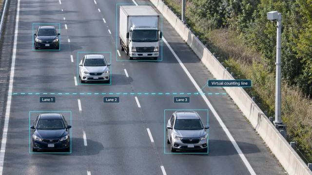
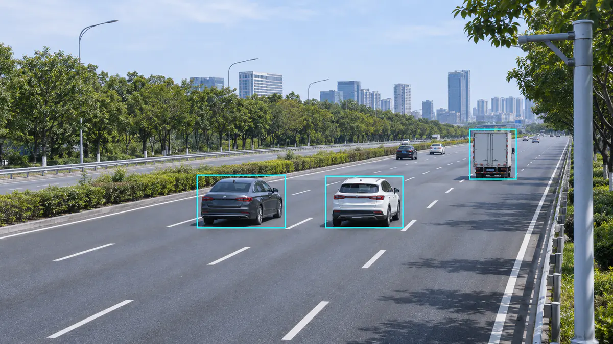
Yes. Multi-target traffic radar can detect and track several vehicles at once, including vehicles in adjacent lanes. The useful test, however, is whether each output stays associated with the right vehicle where your application needs the data. A large target-capacity figure alone does not prove that two close vehicles will always remain separate, or that a small car will remain observable behind a truck.
For side-by-side traffic, check vehicle and lane association. For close following, check what happens as the vehicles approach, travel together and separate. For truck occlusion, first examine the view from the radar mounting point. This guide explains what to inspect, which changes to try first and what to record during commissioning.
1. Target capacity and vehicle separation answer different questions
The HC-M150 multi-lane traffic radar, for example, lists up to 64 simultaneously tracked objects. That describes tracking capacity. It is not a promise that every arrangement of 64 vehicles will produce equally good separation, and it is not a limit of 64 vehicle passages per minute.
Separating nearby vehicles depends on the information available from their range, direction, radial motion and returns, together with detection and tracking processing. Two cars can look clearly separated in a video while presenting a less favourable geometry from the radar pole. Conversely, vehicles that are close in one measurement dimension may differ in another.
Accurately measuring one vehicle is also different from resolving two nearby vehicles. Texas Instruments distinguishes these concepts in its explanation of range and angular resolution. For the broader technical background, see our guide to radar resolution. Neither a single-target accuracy figure nor a resolution number from another device establishes the result at your site.
2. Side-by-side vehicles: verify the association, not just two boxes
Cars in adjacent lanes can have similar speeds and longitudinal positions. Their lateral positions and directions relative to the radar then become particularly useful. For the same lateral spacing, angular separation generally becomes smaller farther from the sensor. A successful near-range check therefore does not establish the same result at the far end of the required road section.
Review a continuous side-by-side passage and check four things:
- One vehicle, one corresponding object: each car should have its own appropriate object record, rather than one record jumping between them.
- Correct lane assignment: a vehicle travelling steadily within a lane should not repeatedly switch to its neighbour’s lane in the output.
- Independent movement: when one car accelerates, slows down or leaves the monitored section, the other car’s output should still follow its own movement.
- No duplicate vehicle records: multiple returns from one car should not be mistaken for several separate vehicles by the application.
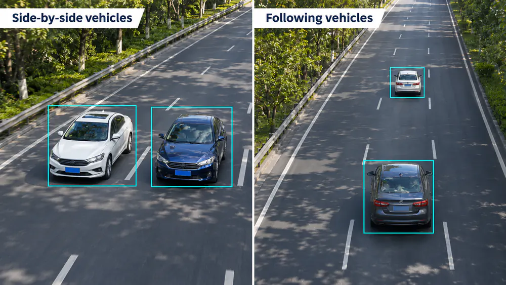
Check side-by-side and following vehicles separately; review the continuous passage rather than a single frame.
If two correctly positioned objects are assigned to the wrong lanes, inspect lane calibration. If only one object is present in the source output during a visible two-car passage, investigate observability, separation and output filtering. Changing a lane label cannot recover a vehicle that is absent from the source records.
Also distinguish a point cloud from an object list. Several reflection points on a truck do not necessarily represent several vehicle tracks, and several vehicle-shaped boxes in a display do not, by themselves, prove correct association over time.
3. Close following: inspect the whole passage through the measurement position
There is no single minimum bumper-to-bumper gap that can be applied to every radar installation. Road spacing is not always the same as separation along the radar’s line of sight. Pole position, viewing direction, vehicle size, relative speed and the strength of each vehicle’s return all affect the observation.
With two closely following vehicles, inspect the approach, the period of close travel and the separation afterwards. Check whether two corresponding objects remain available at the position that matters to your application. A temporary merge upstream and a missing vehicle at the counting line are different findings, although the first can contribute to the second.
| What you observe | What to check next | What establishes the application impact |
|---|---|---|
| Two vehicles become one output object | Visibility from the sensor, unequal returns, object merging and active output filters | Whether each vehicle still produces the required record at the measurement position |
| A position or speed switches between the two vehicles | Continuous vehicle-to-object association against synchronised video | Whether data are attributed to the wrong vehicle |
| A vehicle receives a new ID after the pair separates | When the old track ends, when the new one starts and how passage events are created | Whether the change causes a missed or duplicate event |
| The total count looks correct despite individual mismatches | Missed vehicles, extra records and wrong-lane assignments separately | A vehicle-by-vehicle comparison; errors can cancel in the total |
For an application requiring independent output during close following, define the relevant vehicle combination, gap, speed, road section and installation before testing. A screenshot of two objects in light traffic does not answer that requirement.
4. Truck occlusion: check the mounting view before adjusting sensitivity
If a small car disappears when a truck passes, first inspect the geometry from the radar location. The issue may involve physical occlusion, a much stronger neighbouring return or object processing. Increasing sensitivity or choosing a higher target-capacity model does not guarantee a usable observation of a hidden car.
Compare the period before the truck arrives, the interval alongside or behind it and the recovery afterwards. An issue that consistently follows the truck’s position points to a different investigation from an issue that also occurs at the same road location in light traffic.
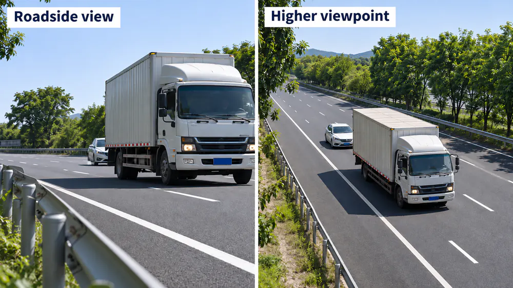
Inspect the truck and car from the proposed sensor position; changing the viewpoint also requires a new coverage check.
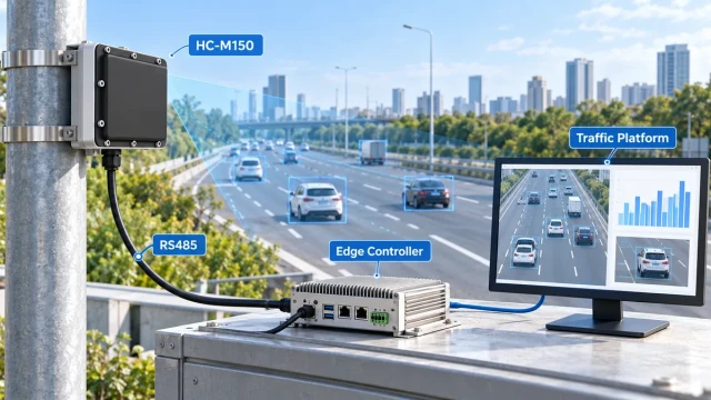
For a standard fixed HC-M150 installation, 4–6 metres is the usual starting height. Roadside, overhead and road-centre positions are possible with the appropriate alignment. A low installation around 1 metre can suit portable roadside speed-measurement equipment, but its far-range view and susceptibility to vehicle occlusion differ from a higher fixed installation. The HC-M150 installation and alignment guide explains those mounting choices.
A higher or differently placed sensor may improve the view, but it also changes the observation geometry and near coverage. Recheck the entire required section after moving it. When the same pole cannot provide a usable view of the required vehicles, evaluate a different pole position, measurement section or additional observation point. A longer detection-range specification alone is not evidence that the obstruction has been solved.
5. A continuing track does not always mean a fresh measurement
A tracker can predict a vehicle’s position from its previous motion during a short interval without an associated measurement. The track may therefore remain visible while it is being maintained by prediction. MathWorks describes this general process as track coasting; that explanation does not establish the internal algorithm or timing of a particular traffic radar.
If your acceptance test needs to distinguish measurement updates from prediction, first confirm whether the device and receiving software expose a suitable status. Without that information, describe the track continuity you can observe rather than claiming uninterrupted detection throughout the occlusion.
Once a hidden vehicle becomes observable again, it may be associated with the previous track or receive a new ID. An ID change is worth investigating, but it does not automatically prove a missed count. Equally, an unchanged ID does not prove that every intermediate position was measured correctly. A radar target ID is a track identifier, not a permanent vehicle identity.
Our radar object-tracking guide explains detection, association and track management in more detail. In the application test, keep the main question concrete: did the correct vehicle produce the required position, speed or passage record at the required time?
6. Run a field check that can identify the cause
Define the required lanes, road section and output first. Record a continuous reference video and the available radar object and passage records over the same period. Align the time bases and account for display latency. The reference camera needs a clear view of the vehicles being checked; if the truck also hides the car from that camera, use another suitable viewpoint or a different reviewable sequence.
| Traffic condition | Check | Keep for review |
|---|---|---|
| Adjacent-lane vehicles travelling together | Independent association, lane assignment and duplicate outputs | Video, timestamps, positions, speeds, IDs and available lane information |
| Two vehicles following in one lane | Merging or interruption as they approach, remain close and separate | Vehicle order, object changes and records at the measurement position |
| A truck and a partly hidden small car | Whether the interruption follows the obstruction and how output recovers | Mounting view, vehicle positions and the full before-and-after sequence |
| Near, middle and far parts of the required section | Whether the same traffic condition behaves differently with position | Results for each section under the same review method |
Compare the source output with the application result. If the radar provides two valid object records while the platform shows one, inspect receiving, filtering and association in the platform. If the source output itself contains only one object, return to visibility, separation, device configuration and any upstream output filters. A display issue and a missing source observation need different fixes.
For HC-M150 projects, the RS485 vehicle-data integration guide helps distinguish object updates from measurement-line states and interval statistics. For counting acceptance, use the lane-by-lane vehicle-count validation method to check individual passages instead of relying on matching totals.
Use naturally occurring traffic or site-authorised test arrangements. Retain representative difficult passages as well as successful ones, and repeat the same review after an adjustment.
7. If separation is unstable, change the right thing first
- Confirm time alignment. A video frame and a delayed object display can make the right track look attached to the wrong car.
- Map where the issue occurs. Note the lane, distance, truck position and whether the location is near a coverage boundary.
- Check installation and lane calibration. Correct a systematic coordinate offset before redrawing lanes around it. If positions are correct but lane labels are wrong, inspect the lane boundaries.
- Check filtering and event creation. Confirm that required vehicles are not discarded by active device or platform conditions, and that track changes are not counted as new vehicle passages automatically.
- Save the configuration, change one relevant setting and retest. Ask the technical team to review recordings before altering object-processing parameters. Recheck the other lanes as well as the original problem.
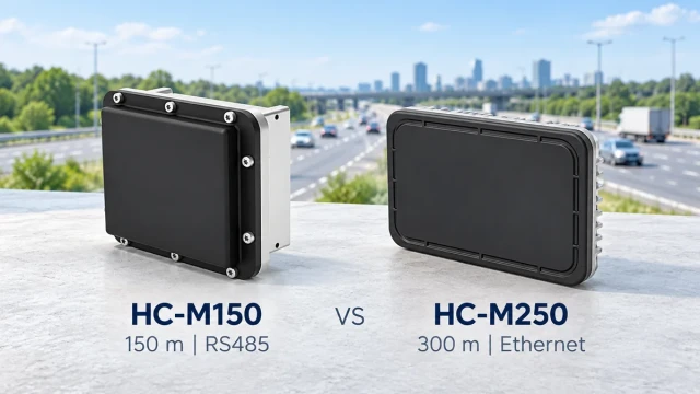
For a longer monitoring section, the HC-M150 versus HC-M250 selection guide helps compare range, interface and application fit. Product selection should follow the required observation and output; a larger capacity or longer range is not, on its own, a solution to close-neighbour separation or truck occlusion.
8. Turn “multi-target detection” into an acceptance requirement
A useful requirement names the vehicles, location and result that must be verified. For example: two vehicles travelling together in the specified adjacent lanes must each produce a correctly associated passage record at the agreed measurement position. Define the test conditions, sample and acceptable error limits with the project team rather than leaving “multi-target” as the entire specification.
| Define | Include |
|---|---|
| Road and mounting | Lane widths, directions, pole position, height, aiming and significant obstructions |
| Vehicle conditions | Side-by-side traffic, close following and mixed truck/car passages that matter to the project |
| Required result | Separate objects, correct lane, position and speed association, passage counts or camera matching |
| Review and retest | Reference video, time alignment, representative samples, error definitions and checks after changes |
For a traffic-flow monitoring project, verify both the vehicle observations and the resulting lane statistics. For camera-linked systems, verify the association with the actual vehicle rather than accepting a moving box as evidence of a correct match.
The decision is whether the radar keeps the required vehicles correctly associated with usable records in your operating section. Send a road layout, proposed mounting position and a short sequence of the traffic condition you need to evaluate when you discuss an HC-M150 installation with our team. Those inputs make it possible to identify the relevant test before selecting or changing the configuration.