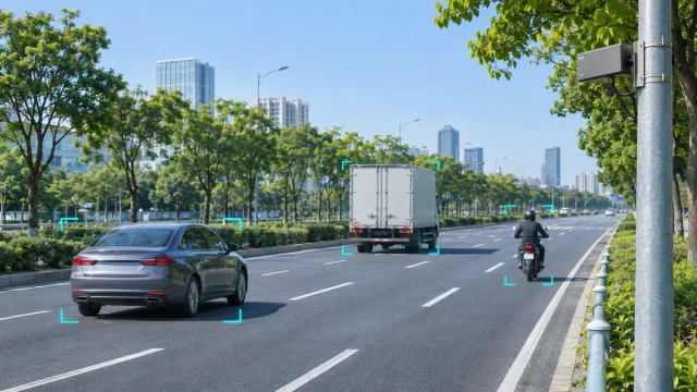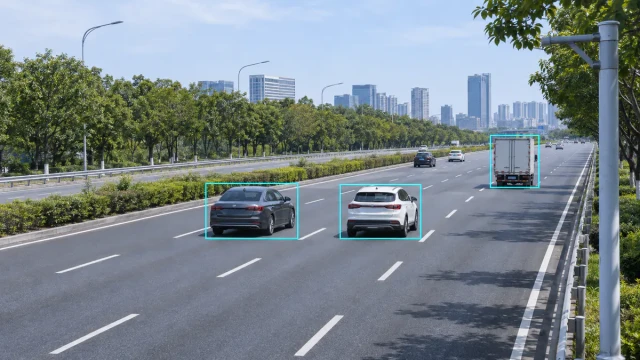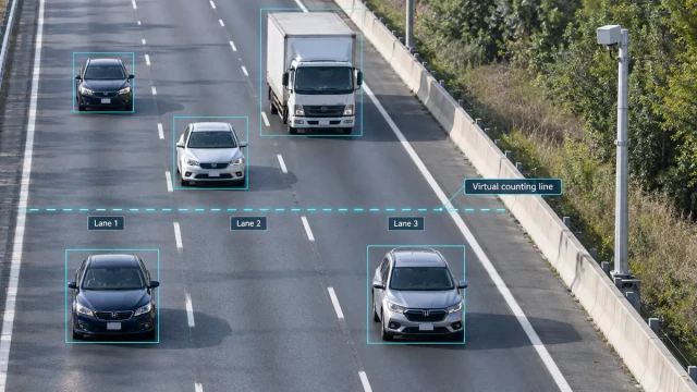
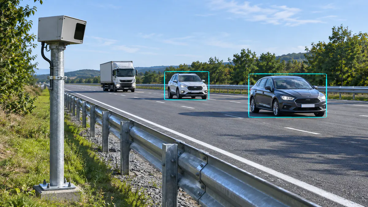
If traffic radar shows a vehicle where the road appears empty, first check whether the extra object is present in the current radar output or appears only in the receiving software. Then compare the records with time-aligned video and the actual road geometry. A guardrail reflection, a displaced coordinate display, an old track left on screen and a duplicate application record need different fixes.
Do not begin by lowering sensitivity or excluding the whole problem area. That can make the display look cleaner while also removing real vehicles. The following sequence helps identify the cause, choose a relevant adjustment and verify that the required detection still works.
1. Find where the extra object first appears
Start with one continuous passage that clearly shows the problem. Compare the earliest available radar object records, the receiving application’s live object list and the resulting display or passage events. Here, “source output” means the records actually received from the radar, not an assumption about access to its internal point cloud.
| Observed pattern | First check | What it tells you |
|---|---|---|
| One source object becomes two objects in the platform | Repeated message handling, multiple data feeds and application association | The duplication may be introduced after the radar output |
| Several vehicles are displaced in a similar way | Coordinate origin, axes, units, mounting alignment and map registration | A shared transformation error is more likely than several independent ghost vehicles |
| A box remains after its source record stops updating | Record age, track prediction, display persistence and deletion handling | The visible box may not represent a fresh observation |
| An additional source object repeatedly appears near a barrier during vehicle passages | Time-aligned video, reflecting surfaces and the complete object history | Multipath is a candidate to investigate, not yet a confirmed cause |
| More reflection points appear on one truck | Whether the interface contains detections, vehicle tracks or passage events | Several points do not automatically mean several vehicles |
If the source contains one object and the platform creates two, investigate the receiving path first. If the extra object is already present in the source records, retain those records and examine the scene, alignment and device configuration. Changing a graphic overlay cannot correct an extra source observation.
The HC-M150 vehicle-data integration guide explains why live object updates, measurement-line information and interval statistics should be handled as different outputs. Comparing unlike outputs can make a normal system look inconsistent.
2. Recognize a possible guardrail multipath pattern
Radar energy can return by an indirect route involving a vehicle and another reflecting surface. The resulting return can be assigned an apparent position that does not correspond to another physical vehicle. Depending on the propagation path, an apparent detection may be farther away or appear beyond a reflecting surface. MathWorks describes these mechanisms in its explanation of multipath radar ghosts.
A steel guardrail is therefore worth inspecting when extra objects repeatedly accompany vehicles near it. But an off-road box alone does not prove multipath: a shifted coordinate system can also put a real vehicle beyond the road edge.
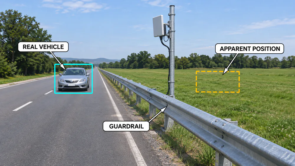
Review repeated passages and ask three questions:
- Does the extra object appear and disappear with a nearby real vehicle? Inspect the period before, during and after the passage, rather than a single frame.
- Does it recur beside the same reflecting section? Compare passages through that section with passages elsewhere in the required coverage area.
- Are most real vehicles correctly positioned while the additional object is elsewhere? If everything is displaced, return to alignment and coordinate conversion first.
An apparently smooth extra track does not establish that a second vehicle exists. Multipath detections can persist and produce false tracks, as discussed in MathWorks’ highway multipath tracking example. That example demonstrates the phenomenon; it does not establish the filtering method or performance of a particular roadside radar.
3. Rule out timing, alignment and stale-track errors
First match the time. A delayed video stream compared with a current coordinate display can make the correct object look attached to empty road. Use shared timestamps where available, account for the video and processing delays, and compare a recognizable passage through a fixed reference position. A common time mismatch often shifts several moving vehicles along their paths.
Then check the geometry. Confirm the radar’s position and pointing direction, the coordinate origin and axis conventions, and any conversion into the application’s road map. Check known road features across the required section. If a small orientation error produces a larger lateral discrepancy farther away, shrinking the detection area will not correct that transformation. Use the HC-M150 installation and alignment guide when reviewing that device’s mounting and setup.
Finally, check record age. A display may retain an old object, and a tracker may predict a position during a gap without an associated measurement. MathWorks calls the latter process track coasting. Only distinguish measured and predicted updates if the actual interface exposes enough information; an unchanged ID is not proof of fresh measurement.
Inspect the latest received record and the display’s update or expiry behaviour. If the source object has ended but its box remains indefinitely, correct that handling before moving the radar. For a fuller distinction between detections, association and tracks, see the radar object-tracking guide.
4. Record one passage that can be checked end to end
Record a continuous road video and the available source object records over the same interval. Include the lead-in before the apparent extra object, the full passage and the period after it disappears. The camera must show the relevant lane and roadside area; a region hidden from the camera is not confirmed empty.
Mark the radar position, guardrail, lane boundaries and measurement position on the site layout. Preserve the original records as well as the screen recording. A screen recording shows what the operator saw, but it may not reveal duplicated processing, lost records or stale display state.
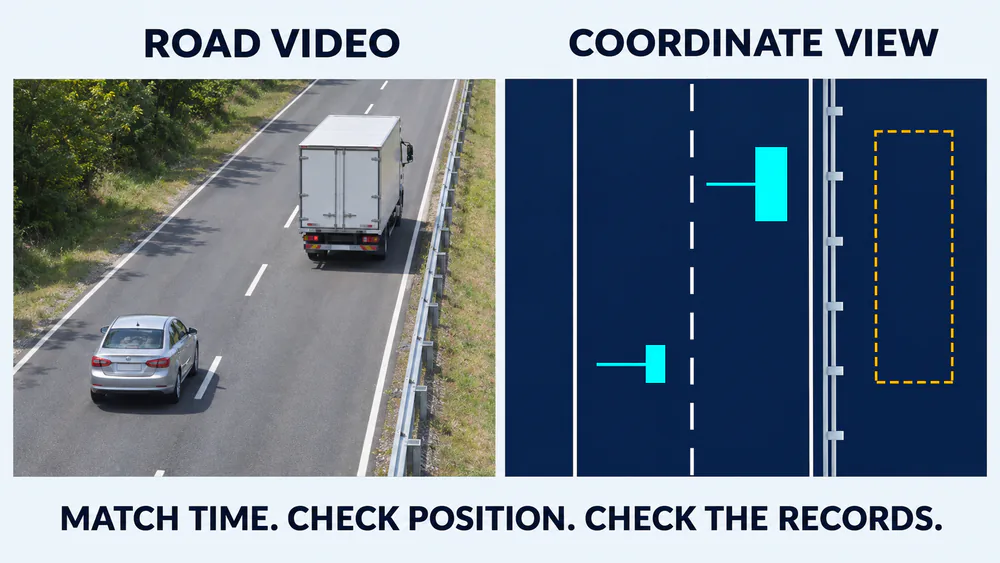
Match the time, verify the coordinate mapping and inspect the records before deciding where the extra object originates.
- Identify the physical passage: note the lane, vehicle order and a visible reference crossing.
- Identify the corresponding source object: follow its available position, speed, direction and ID through the same interval.
- Locate the apparent extra object: establish when it first appears, where it moves and whether its timing follows another vehicle.
- Trace the application result: determine whether the extra object only appears on screen or also creates a count, trigger or other event.
Repeat the review for several comparable passages and include correctly handled passages. For closely following vehicles or a car beside a truck, use the multi-vehicle separation field guide to avoid mistaking merging, occlusion or an ID change for a separate ghost-target problem.
5. Make the adjustment that matches the evidence
Change one factor at a time and save the original setup. Keep the firmware and configuration version, alignment values, lane layout, active area and application settings with each recording. Otherwise, a better-looking screen may not tell you which change helped.
If the evidence points to a reflecting section, evaluate whether another mounting position or viewing direction can reduce the problematic geometry while preserving the required road view. There is no universal height or angle that removes every reflection. Moving the sensor also changes its coordinate relationship with the road, so update alignment and lane calibration before judging the result.
If the current area includes a side road, pavement or verge that the application does not need, narrow the relevant output or processing area where the equipment supports it. Check which stage a setting affects. Hiding an object in the application is different from excluding it from device output, and either may differ from the rules used to generate passage events.
Do not exclude a required lane or road edge merely because the symptom occurs there. If the apparent extra track overlaps useful coverage, investigate the geometry and records rather than masking the whole strip. A boundary that works for one car can exclude a different vehicle or turning movement.
Sensitivity or detection-related settings may be relevant when they are documented and available. Use a controlled before-and-after check, because reducing unwanted responses can also reduce useful ones. Recheck smaller vehicles and the farther required section as well as the large vehicle that first exposed the problem. Request device-specific advice before changing undocumented tracking or filtering settings.
6. Verify the application result, not just the cleaner display
An extra displayed track and an extra vehicle count are different findings. Determine which one your application must prevent. In a traffic-flow monitoring system, inspect the individual passage records and their lane assignments. In a speed-enforcement integration, inspect which physical vehicle is associated with the relevant measurement and camera event.
| After the change, check | Evidence to compare | Result that needs more work |
|---|---|---|
| Apparent extra objects | Source records and display at corresponding times | The box disappears from view but still generates an event |
| Required vehicles | Vehicle-by-vehicle reference against the required output | Real vehicles are now missing with the new configuration |
| Lane and event association | Each passage, assigned lane and resulting event | Totals look right, but individual vehicles are duplicated or assigned incorrectly |
| Coverage near boundaries and at distance | Comparable passages in each required part of the road | The improvement is limited to the short section used for adjustment |
Record missed passages and extra passages separately; one can cancel the other in a total. The lane-by-lane counting validation method provides a practical way to make that comparison. Assess the change against the agreed lanes, vehicle types, output and operating conditions, rather than treating the absence of visible boxes as the acceptance criterion.
7. Send a reviewable evidence set when the cause remains unclear
If the extra object remains in the source output after timing and alignment checks, send the supplier a short, complete evidence set. Include the problem passage and a nearby correctly handled passage, together with:
- The device model, firmware version, configuration and receiving software version.
- A site layout and photographs showing the mounting position, direction, lanes, guardrail and other large reflecting surfaces.
- The continuous reference video, original received records and a note explaining their time relationship.
- The exact interval and available object IDs to examine, including the before-and-after history.
- The application impact: extra display object, duplicate passage, wrong-lane event or incorrect vehicle association.
- The single-setting or mounting changes already tried, with the corresponding results.
For an HC-M150 traffic radar installation, this lets the review start from the actual mounting, configuration and received vehicle data. A photograph of a box beside a guardrail is useful context, but it cannot by itself identify the internal processing cause or establish which setting should change.
8. Common field questions
Does a target beyond the guardrail prove multipath?
No. First verify the coordinate mapping and the camera view. A repeatable additional source object that accompanies real vehicles near a reflecting surface is stronger evidence for investigating multipath than one off-road box in a screenshot.
Should every target outside the lane be filtered out?
Only if that area is genuinely outside the application’s required coverage and the relevant filtering stage is understood. A shared alignment error can put real vehicles outside the drawn lane. Correct that error before using the lane boundary to discard them.
Is a lower sensitivity setting the quickest fix?
It may suppress a symptom, but it does not identify its cause. First check whether the extra object originates in the radar records or the receiving application. After any relevant sensitivity change, verify that required vehicles are still detected and assigned correctly.
Should an apparent ghost be counted as a false alarm?
Define the output being assessed. Count an extra vehicle passage as an extra passage; record an unwanted display object separately if it produces no passage. For a camera-trigger application, review the trigger and vehicle association. Clear definitions make the test useful and prevent a clean total from hiding individual errors.