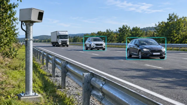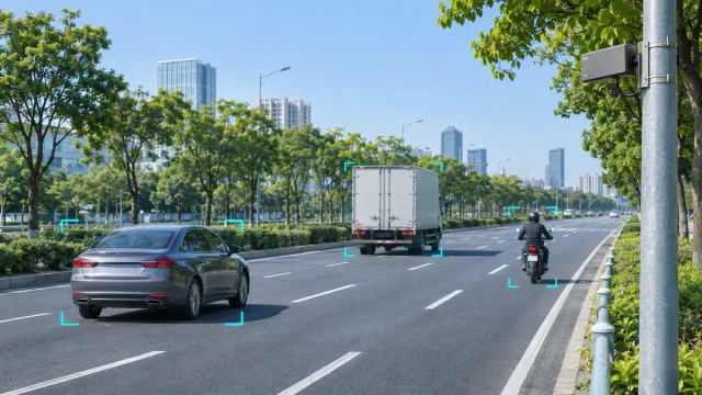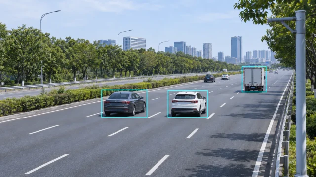
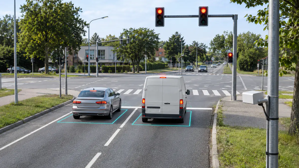
When a vehicle waits at a red light without being served, check three separate states: the detector’s observation, the controller’s received input and the controller’s call or phase service. A car visible in a sensor display does not establish that the correct controller input is active. An active input does not, by itself, require an immediate green signal.
Use one recorded arrival, stop, wait and departure to trace those states. This guide explains how to investigate missed calls, calls without an intended vehicle and an apparently stuck presence indication. It applies to the detection chain rather than to one sensor brand. For the technology overview, see how traffic light sensors work.
Use authorised diagnostics and the site’s approved procedures. Cabinet testing and changes affecting live signal operation belong to qualified personnel; do not bypass detection or alter clearance intervals to make a test appear successful.
1. Identify the first state that disagrees with the road
Before changing a zone or sensitivity setting, identify the lane, intended movement, detection zone, output channel, controller input and assigned phase. Save the active configuration and timing-plan identity. A valid observation routed to the wrong movement is a mapping problem, not necessarily a detection failure.
| Road and diagnostic observations | First investigation | What not to assume |
|---|---|---|
| A waiting car is absent from the detector’s relevant zone output | Coverage, stationary detection, occlusion and zone conditions | A healthy network connection proves vehicle detection |
| The detector’s output is active, but the expected controller input is not | Interface, intermediate processing and channel mapping | Higher sensor sensitivity will repair the input path |
| The correct input is active, but the intended phase has no corresponding call | Input assignment, controller configuration and how the diagnostic defines a call | Every highlighted input is assigned to the movement being watched |
| A call is registered, but green has not appeared | Controller operation, phase eligibility and service history | The detector has failed simply because the vehicle is still waiting |
| The road is empty, but an indication remains active | Which layer remains active and whether it represents a live input, retained call or fault response | All persistent indications mean a stuck sensor |
Write down the first point where the expected transition is missing. If the available screen only shows a processed phase call, obtain the appropriate input or detector diagnostic before drawing a conclusion about the upstream hardware. Our radar traffic-detector guide explains the difference between object, presence and other traffic outputs.
2. Missed calls: check the actual waiting position
If a car is detected on approach but disappears after stopping, first check the waiting position and stationary-detection requirement. An upstream zone may be crossed successfully and still leave the stopped vehicle outside the area used to request service. Inspect the real stop line and where drivers actually wait, rather than relying only on a drawn map.
Geometric coverage and sensing capability are separate checks. A zone drawn over a stationary car does not prove the sensor can maintain the required presence output. FHWA distinguishes motion-oriented Doppler radar from presence-detecting radar in its sensor technology reference. Confirm the deployed device’s documented behaviour instead of inferring it from the word “radar”.
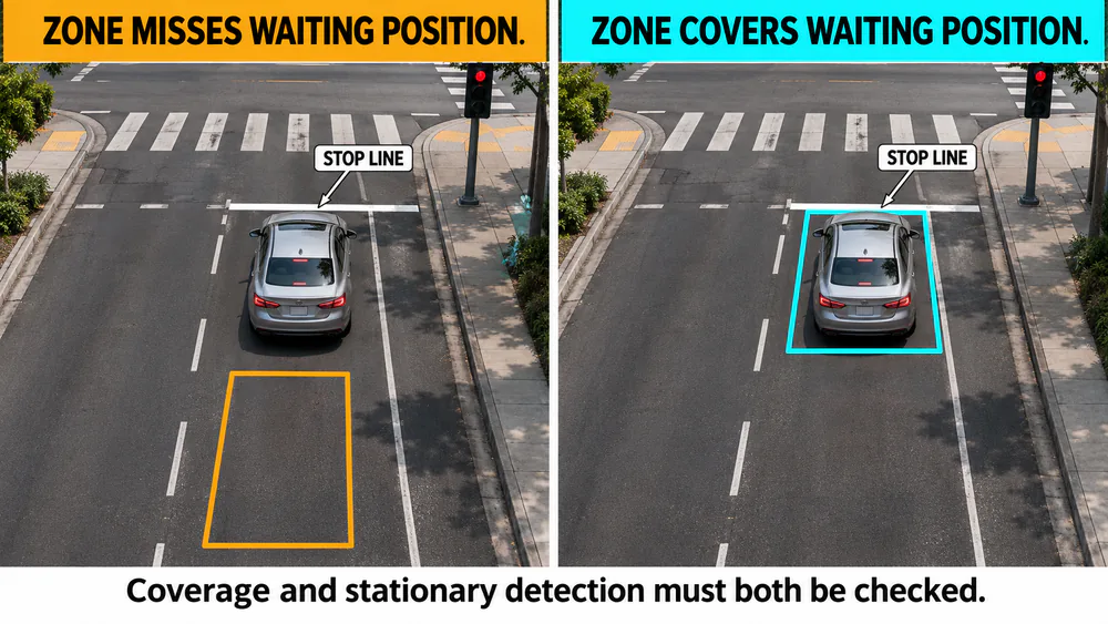
Verify both the waiting-position coverage and the deployed detector’s stationary-detection capability.
- Watch a lone vehicle stop: record whether the intended zone output stays appropriate throughout the wait.
- Check the lane edges: include vehicles waiting slightly off the lane centre without expanding coverage into a neighbouring movement.
- Check a queue: establish whether a larger vehicle or another part of the installation obstructs the required view.
- Review the configured conditions: examine direction, movement or speed-related conditions where available; a condition suited to moving vehicles may not suit a waiting vehicle.
Where detector technology permits, compare the observed road position with the actual configured detection area. For in-pavement sensors, inspect the installed detection footprint and approved diagnostics rather than assuming an on-screen zone can be moved. If the issue is specific to roadside radar mounting, the HC-M150 installation guide provides a device-specific alignment example; it is not a claim that every radar supports stop-line presence detection.
3. Detection is present, but the controller input is missing
If the correct detector output changes while the expected controller input does not, trace that transition through the interface. A working vehicle list or video overlay is not necessarily the output connected to the controller. Some installations use an intermediate processor to convert observations into zone or channel states.
Identify the configured output type, receiving interface and channel assignment. Then compare the detector-side transition, any intermediate application’s transition and the controller’s input diagnostic over the same arrival and departure. Use the actual interface documentation; do not assume that Ethernet connectivity supplies a compatible controller message or that a serial vehicle-data stream is a direct presence input.
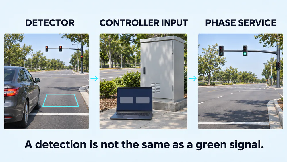
Compare the detector output, received input and phase-service records separately; one state does not establish the next.
Check whether the event is sent to the intended channel, whether the receiving device reports it and whether the diagnostic view is showing current data. Where an output is a brief pulse, a slowly refreshed display may miss the transition. Use event records or a suitable approved diagnostic rather than extending every output as an experiment.
For target-data applications, our traffic radar data-integration guide helps distinguish individual object updates, measurement-line information and statistics. A correct flow total does not establish that a separate controller-presence path is working.
4. False calls: find the source of unwanted actuation
When the intended lane is empty but a detector output activates, record what else is happening at that instant. Check neighbouring traffic, turning vehicles, the relevant roadside area and the detector’s health indications. An empty lane is not the same as an empty detection footprint.
For configurable area detection, compare the zone with actual lane and movement boundaries. Follow one vehicle through each nearby movement and note which zone and output respond. If an adjacent movement repeatedly activates the wrong channel, distinguish an oversized or misplaced zone from a correctly detected vehicle assigned to the wrong output.
For video detection, compare the event with the camera view, scene visibility and diagnostic recording. For radar, compare the current source observations with the area that generates the output. The traffic radar false-target checks explain how to investigate apparent extra objects without immediately attributing them to multipath. For loops or magnetic sensors, use the sensor’s fault and maintenance diagnostics; changing a software polygon cannot repair an in-roadway sensing problem.
If no current detector output corresponds to the displayed call, move downstream. The controller may be retaining an earlier actuation or generating service through its configured operating logic. Reducing detector sensitivity cannot remove a call that does not originate in a current detection.
5. Stuck presence: distinguish a live input from a retained call
Ask exactly what remains active after the vehicle leaves. Compare the sensing or zone state, the transmitted output, the controller input and the call indication. These are not interchangeable names for the same bit of information.
A presence output normally relates to occupancy of the configured detection area, while a pulse reports an actuation briefly. A controller can also retain an actuation according to its configured memory mode. FHWA’s detector operating and controller memory concepts explain why a call can remain after a detector actuation ends. These established concepts are background; use the installed controller’s current documentation for its exact diagnostics and configuration.
- The zone remains occupied: inspect what the sensor is still observing and whether its output history matches the road.
- The zone clears but an intermediate output stays active: examine documented hold, extension, stale-data and release handling in that stage.
- The detector output clears but the controller input stays active: investigate the receiving interface and its diagnostic or fault state.
- The input clears but the call remains: check call memory and operating logic before declaring a stuck detector.
A communications outage may also invoke a configured fault response somewhere in the chain. Record the device health, connection state and time of the transition; do not treat a failure response as a real vehicle observation. Follow the approved failure policy rather than simply forcing the indication off.
6. The call is valid, but the vehicle still waits
Once the correct input and call are confirmed, investigate service rather than repeatedly changing the sensor. Record the requested movement, actual phase sequence, active plan and relevant controller events. Establish whether the request remains pending, is being served under another assignment, or is affected by the configured operation.
Controller operation includes timing, coordination and other service conditions. Recall can also request a phase without a current detector actuation. FHWA’s controller timing and parameter reference explains these distinctions. The correct interpretation comes from the active plan and installed controller, not from a universal number of seconds a detected vehicle should wait.
Compare a successful service with the problematic sequence under the same operating plan. If the issue only occurs after a plan change, retain the configuration and event history from both periods. If a particular lane activates the wrong phase, check the mapping before blaming waiting time on sensor range or sensitivity.
Do not shorten clearance times or remove safety-related conditions to test a detection hypothesis. First establish the input-to-call relationship and have the responsible signal engineer assess the service behaviour through the approved process.
7. Run an arrival-to-departure check after the change
Record continuous reference video together with the available detector, interface, input and call diagnostics. Align their times and account for display latency. Mark the relevant lane, zone and movement. A correct total vehicle count or a single successful green indication is insufficient to verify the whole sequence.
| Test condition | Compare | What must be explained |
|---|---|---|
| A lone vehicle arrives and waits | Road position, zone output, controller input and call | Whether the required request is generated and handled throughout the wait |
| The vehicle receives service and leaves | Departure, output release, input state and call handling | Any retained state and whether it matches the configured operation |
| Only a neighbouring movement passes | Relevant zone and channel responses | Unwanted requests or incorrect movement assignment |
| A larger vehicle and smaller road users are present | Coverage and required outputs for each relevant user | Occlusion or exclusions introduced by the adjustment |
| The affected operating plan is active | Input, call and phase-service history | Why the result differs between plans or periods |
Change one documented setting at a time and preserve the before-and-after configuration. Define acceptance around the required movements and road users, including any motorcycles or bicycles the project must serve. Do not call a sensitivity reduction successful merely because an unwanted indication disappears.
If traffic statistics are also used by the traffic monitoring system, check them separately. Our vehicle-count validation method addresses passage accuracy; controller-call behaviour requires the state-by-state check above.
8. Keep the evidence needed to finish the repair
Retain the lane and movement layout, zone-to-output-to-input-to-phase mapping, device and firmware versions, interface details, active configuration and timing-plan identity. Add a short time-aligned recording of the failed sequence and one correctly handled sequence, noting which state first differed from the expected behaviour.
Then direct the finding to the relevant part of the system: coverage or sensing when the required observation is missing; integration when the output does not reach the correct input; controller configuration or operation when the input and call are valid but service differs from the plan. This makes the next action specific and avoids replacing a healthy sensor to solve a downstream fault.
The practical completion criterion is a verified arrival, wait and departure sequence for the required movement, with unwanted calls checked separately and any retained or failure states explained. No single sensor specification, connection indicator or clean screenshot establishes that result.