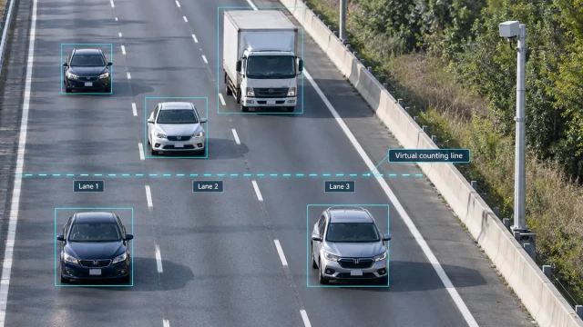

A curve warning system detects vehicles approaching a bend and provides an active warning when their speed or movement creates a potential road-safety concern.
Unlike a static curve sign, a dynamic system responds to actual traffic. A radar sensor measures the speed of an approaching vehicle, a controller compares that speed with a configured threshold, and roadside equipment displays a warning only when activation conditions are met.
The warning may take several forms:
- Flashing beacons
- A dynamic “SLOW DOWN” message
- A vehicle-speed display
- Sequential illuminated chevrons
- A variable message sign
- A remote event notification
The effectiveness of the system depends on much more than the radar’s maximum detection distance. Sensor alignment, warning threshold, sign location, activation duration, road geometry and controller logic all influence the driver’s opportunity to recognise and respond to the warning.
This guide explains how radar-based curve warning systems work and what system integrators should consider during design, installation and commissioning.
What Is a Curve Warning System?
A curve warning system is a roadside safety system intended to increase driver awareness before or within a horizontal curve.
Static systems use fixed signs, advisory speed plaques, delineators, pavement markings or chevrons. Dynamic systems add vehicle detection and active warning equipment.
A typical dynamic curve warning system includes:
- A vehicle speed sensor
- A controller
- A warning sign or display
- Flashing beacons or illuminated chevrons
- Power equipment
- Optional communications and event logging
The system measures an approaching vehicle and activates a warning according to site-specific rules.
The warning does not control the vehicle. It gives the driver additional information and draws attention to the curve or advisory speed.
Why Use a Dynamic Warning Instead of a Static Sign?
Static warning signs communicate continuously, regardless of how fast an individual vehicle is travelling.
A dynamic system can remain inactive for vehicles below the configured threshold and activate only for vehicles that meet the warning condition. This makes the message more relevant to the approaching driver.
Dynamic activation can also help reduce unnecessary flashing and avoid turning an active warning into background roadside information.
A radar-based system may support:
- Individual vehicle speed measurement
- Direction filtering
- Speed-dependent warning messages
- Different warning levels
- Event counts and speed statistics
- Remote monitoring
- Integration with illuminated chevrons
- Optional camera or traffic platform connection
Dynamic warnings should supplement—not automatically replace—the signs, delineation and road treatments required by the relevant road authority.
Main Components of a Radar Curve Warning System
Radar speed sensor
The radar detects an approaching vehicle and measures its radial speed.
Depending on the product, it may provide:
- Vehicle speed
- Approach or departure direction
- Speed unit
- Threshold output
- Serial data
- Digital or relay trigger
- Basic event information
A simple curve warning installation may need only one vehicle speed and direction. A multi-lane road may require lane position, coordinates and multi-target tracking.
Controller
The controller receives the radar measurement and applies the activation rules.
Controller logic may include:
- Minimum activation speed
- Maximum displayed speed
- Approach-direction filtering
- Trigger confirmation
- Activation duration
- Retrigger delay
- Sign brightness control
- Event logging
- Fault monitoring
- Communications
The controller should define what happens when radar communication is lost or when the measured value is outside the expected range.
Warning equipment
The warning output may include:
- Flashing beacon
- Dynamic message sign
- “YOUR SPEED” display
- “SLOW DOWN” message
- Curve-symbol display
- Sequential chevron signs
- In-road warning lights
The message must be visible early enough for the driver to perceive it and respond before entering the hazard area.
Power system
Power may come from:
- Utility power
- Solar panels
- Battery storage
- A hybrid solar and utility system
The power design must account for the radar, controller, sign, communications and worst-case beacon duty cycle.
Communication
Some systems operate locally without network access. Others send status and traffic information to a central platform.
Communication options may include:
- RS485
- UART
- Ethernet
- Cellular network
- Radio link
- Digital input and output
- Relay contact
Remote communication can support diagnostics, event statistics and parameter management, but it also introduces cybersecurity and network-maintenance requirements.
How a Radar Curve Warning System Works
A typical operating sequence is:
- The radar detects a vehicle approaching the curve.
- It measures vehicle speed and direction.
- The controller validates the measurement.
- The measured speed is compared with the activation threshold.
- If the conditions are met, the controller activates the warning.
- The warning remains active for the configured time or while the vehicle remains in the monitored approach.
- The controller records the event when logging is enabled.
- The system returns to standby.
More advanced systems may maintain several activation levels.
For example:
- Lower threshold: display the measured speed.
- Higher threshold: display “SLOW DOWN.”
- Critical event: activate additional beacons or remote notification.
The actual logic should be determined by the road authority and the site’s engineering study.
How Radar Measures Approaching Vehicle Speed
Doppler radar measures the frequency shift of radio waves reflected from a moving vehicle.
The radar measures radial velocity—the component of vehicle motion directed toward or away from the sensor.
For accurate speed output, the sensor should be aligned with the intended vehicle path. A large angle between the radar beam and vehicle direction can cause the measured radial speed to be lower than the true road speed unless the system is designed to compensate for that geometry.
Important installation factors include:
- Radar-to-road angle
- Mounting height
- Lateral offset
- Road gradient
- Curve geometry
- Vehicle approach direction
- Beam width
- Detection distance
- Mounting stability
See our Doppler radar guide for a detailed explanation of radial velocity and cosine error.
Selecting the Warning Threshold
The activation threshold should not be selected arbitrarily or copied from another road.
Threshold selection may consider:
- Posted speed limit
- Curve advisory speed
- Observed approach speeds
- Road geometry
- Available sight distance
- Crash history
- Surface condition
- Weather exposure
- Vehicle mix
- Existing signs and delineation
- Road authority requirements
The threshold used to activate a warning does not necessarily have to equal the posted speed limit. Curve advisory speeds and dynamic warning thresholds serve different operational purposes from enforceable speed limits.
A speed study may be needed to understand normal approach behaviour before defining the activation rule.
The threshold should be documented as part of the system design and commissioning record.
Lower and Upper Speed Thresholds
Some systems use more than one threshold.
Lower threshold
The lower threshold may activate a speed display or basic warning.
This can draw attention to the driver’s actual speed without immediately showing the strongest warning state.
Upper threshold
The upper threshold may activate a more urgent message, flashing pattern or “SLOW DOWN” instruction.
A system displaying vehicle speed may also need a maximum displayed value or alternate message. This prevents extreme or obviously invalid measurements from producing an unsuitable sign display.
Threshold behaviour should be tested with:
- Vehicles just below the threshold
- Vehicles just above the threshold
- Repeated vehicles
- Closely spaced vehicles
- Approaching and receding traffic
- Communication interruption
Where Should the Radar Be Installed?
The radar should detect the vehicle early enough for the controller and sign to respond before the driver enters the curve.
The correct position depends on:
- Vehicle approach speed
- Required warning time
- Available sight distance
- Sign location
- Road gradient
- Curve start point
- Detection range
- Radar beam geometry
- Nearby intersections or driveways
Installing the radar too close to the curve may not provide sufficient response distance. Installing it too far away may detect vehicles that turn off, change direction or are no longer associated with the warning location.
The radar does not necessarily need to be mounted in the same cabinet or structure as the warning sign. A separate detection position may provide better measurement geometry.
Warning-Sign Placement
The sign or beacon must be positioned where approaching drivers can see and understand it.
Placement should account for:
- Driver sight distance
- Roadside obstructions
- Vegetation
- Horizontal and vertical curves
- Existing warning signs
- Background visual clutter
- Night visibility
- Sign orientation
- Vehicle approach speed
- Local traffic-control standards
The system designer should not use the radar’s detection distance as the sign-placement distance without a separate engineering review.
Traffic signs and advisory-speed displays must comply with the applicable local standards. In the United States, horizontal alignment signs and advisory-speed plaques are addressed by the current Manual on Uniform Traffic Control Devices.
Types of Dynamic Curve Warning
Speed feedback display
The sign shows the measured speed of the approaching vehicle.
This provides direct feedback and may be combined with a curve symbol or advisory-speed sign.
Speed-activated message
The system displays a message such as “SLOW DOWN” only when the vehicle exceeds the configured threshold.
Flashing beacon
Radar activates beacons mounted around or near a static curve warning sign.
This improves conspicuity without requiring a full variable message display.
Sequential chevrons
Illuminated chevrons flash in sequence through the curve.
The sequence can help identify the direction and path of the bend. Its timing and sign arrangement must match the curve geometry and applicable standards.
Multi-stage warning
A system may combine advance speed feedback with beacons or sequential chevrons closer to the curve.
Each stage requires defined triggering, timing and fault behaviour.
Single-Lane and Multi-Lane Systems
A compact Doppler speed sensor may be sufficient for a single approach where the controller needs one speed value.
Multi-lane roads introduce additional questions:
- Which lane produced the speed?
- Are multiple vehicles present simultaneously?
- Should the warning activate for the fastest target?
- Can the system maintain separate target records?
- Are opposing traffic directions inside the beam?
- Can large vehicles hide smaller vehicles?
- Is lane-specific warning required?
A single-speed-output radar is not equivalent to a multi-target tracking radar.
For roadside feedback and warning applications, the HC-TR20 speed radar outputs vehicle speed and direction for integration with signs and controllers.
HC-TR20 is intended for speed feedback and warning systems. It should not be treated as a multi-target lane-tracking radar.
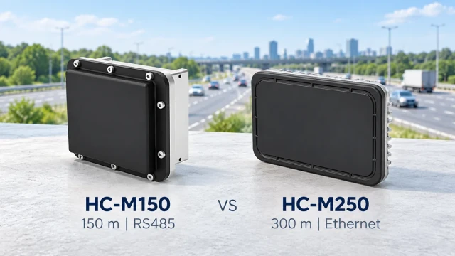
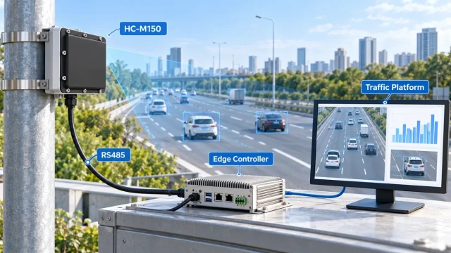
Where a system requires coordinates, individual target IDs or multi-lane association, an HC-M150 multi-lane traffic radar or another suitable tracking sensor should be evaluated.
Direction Filtering
A curve warning radar may observe vehicles travelling in both directions or vehicles on a nearby road.
Direction filtering allows the controller to respond only to the intended approach.
The system should be tested for:
- Approaching vehicles
- Receding vehicles
- Opposing traffic
- Vehicles reversing
- Vehicles turning into nearby access points
- Reflections from vehicles on adjacent roads
Incorrect direction configuration can cause unwanted activation or missed warnings.
Preventing False and Repeated Activation
A practical controller may use several rules to stabilise operation:
Measurement confirmation
Require more than one consistent radar measurement before activating the warning.
Minimum activation time
Keep the sign active long enough for the driver to perceive the message.
Retrigger behaviour
Define whether each new vehicle extends the warning duration.
Hysteresis
Use separate activation and deactivation thresholds to avoid rapid switching when speed fluctuates near the threshold.
Direction and range gates
Accept measurements only from the intended direction and detection area.
Plausibility checks
Reject speed values outside the expected operating range.
These settings must balance responsiveness and false-trigger control. Excessive filtering may delay the warning, while insufficient filtering may cause unstable operation.
Curve Warning System Interfaces
The radar and controller may exchange different types of data.
Serial speed output
The radar sends measured speed and direction through RS485 or UART. The controller applies the threshold and sign logic.
Warning output
The radar or controller produces a digital high/low signal when an activation condition is met.
Relay contact
A relay closes to activate beacons or another roadside device.
Network message
A network-capable system sends target or event data to a central platform.
Before integration, confirm:
- Electrical voltage levels
- Serial baud rate
- Data format
- Speed units
- Direction convention
- Message interval
- Timeout behaviour
- Fault output
- Power-up state
- Recovery after communication loss
Solar-Powered Curve Warning Systems
Remote curves may not have convenient utility power.
A solar system must be sized for:
- Radar consumption
- Controller consumption
- Sign and beacon load
- Night operation
- Expected activation frequency
- Communication equipment
- Seasonal sunlight
- Battery temperature
- Required autonomy
The sign normally consumes more power than the radar, especially when bright LEDs or multiple sequential chevrons are used.
Power calculations should use the expected duty cycle and worst seasonal conditions—not only average sunshine.
The controller should monitor battery voltage and provide a defined low-power or fault state.
Optional Camera Integration
A curve warning system may use a camera for:
- Event review
- Traffic studies
- Visual confirmation
- System evaluation
- Recording unusual events
The camera should not automatically be described as enforcement equipment. Enforcement requires its own legal, evidential and approval process.
If radar and video are associated, the system should synchronise:
- Timestamp
- Event ID
- Trigger timing
- Direction
- Measurement zone
For projects requiring combined target data and images, see our guide to radar-video fusion.
System Monitoring and Event Logging
Useful logged information may include:
- Date and time
- Measured speed
- Direction
- Warning state
- Activation duration
- Radar communication status
- Battery voltage
- Controller faults
- Sign faults
- Configuration changes
Aggregated data can help the road authority evaluate:
- Number of warning activations
- Speed distribution
- Peak periods
- System availability
- Changes after installation
The system should avoid collecting unnecessary personal data. Radar speed and event records do not require conventional vehicle imagery unless a camera is deliberately added.
Commissioning and Field Validation
A curve warning system should be commissioned as a complete system rather than testing the radar and sign separately.
Radar validation
Verify:
- Speed against a suitable reference
- Approach and departure direction
- Minimum and maximum detection distance
- Beam coverage
- Performance for motorcycles, cars and trucks
- Behaviour near the speed threshold
- Adjacent-road rejection
Controller validation
Verify:
- Threshold logic
- Hysteresis
- Warning duration
- Retrigger behaviour
- Communication timeout
- Power restoration
- Fault handling
Sign validation
Verify:
- Day and night visibility
- Message correctness
- Brightness control
- Beacon pattern
- Sequential timing
- Viewing angle
Full-system validation
Drive through the approach at different speeds and confirm:
- Correct vehicle measurement
- Correct activation threshold
- Sufficient warning time
- Stable display
- No unwanted activation from departing traffic
- Recovery after each event
Acceptance criteria should be documented before testing.
Common Curve Warning System Problems
Radar is aimed across the vehicle path
A large angle can reduce the measured radial speed.
Warning activates too late
The sensor, sign or trigger point may be too close to the curve.
Opposing traffic activates the sign
Direction filtering or beam orientation may be incorrect.
Large trucks dominate the measurement
The radar may be selecting the strongest target rather than the intended lane or vehicle.
The sign flashes continuously
The threshold may be too low, direction filtering may be incorrect or stationary interference may be entering the detection logic.
Solar battery repeatedly discharges
The design may underestimate sign duty cycle, winter sunlight or communication load.
Speed display changes rapidly
The controller may be switching between targets or accepting unstable measurements without confirmation.
Warning no longer matches the road
Lane layout, signs or road geometry may have changed without recommissioning the system.
How to Select a Radar for Curve Warning
Ask the following questions:
- Is the road single-lane, two-lane or multi-lane?
- Must the radar measure approaching vehicles only?
- Is one speed value sufficient?
- Is lane position required?
- Are several vehicles likely to be present simultaneously?
- What detection distance is required?
- What mounting angle is available?
- Does the controller require serial data, relay or digital output?
- Will the system be solar powered?
- Does the project need event logging?
- How will speed measurement be validated?
- Which traffic-control standards apply?
Do not select the radar solely by maximum distance. The required output, road geometry and controller interface are equally important.
Frequently Asked Questions
What is a dynamic curve warning system?
It is a traffic-safety system that detects an approaching vehicle and activates a warning according to vehicle speed or another measured condition.
Can radar trigger flashing curve signs?
Yes. Radar speed data can be sent to a controller that activates beacons, dynamic messages or sequential chevrons.
Should the warning activate at the posted speed limit?
Not necessarily. Activation thresholds should be determined from advisory speed, road geometry, speed studies and the road authority’s engineering requirements.
Can one radar monitor both traffic directions?
Some radar sensors can detect approaching and receding vehicles. Whether both directions should be used depends on the road layout and warning logic.
Can HC-TR20 track several lanes independently?
No. HC-TR20 is intended to output vehicle speed and direction for signs and warning systems. Applications requiring individual coordinates and multi-target lane tracking need a suitable tracking radar.
Can the system operate from solar power?
Yes, if the solar panel, battery and controller are sized for the radar, sign, communications and expected activation duty cycle.
Does a curve warning system replace static signs?
Normally no. Dynamic warning equipment supplements the signs, advisory-speed information and delineation required by the relevant road authority.
Is a curve warning radar an enforcement device?
Not automatically. Warning and enforcement systems have different objectives, certifications, evidence requirements and operating procedures.
Conclusion
A radar-based curve warning system measures approaching vehicle speed and activates a relevant warning before the vehicle enters a hazardous bend.
A successful system requires coordination between the radar, controller, sign, power supply and road geometry. Detection distance alone is not enough. The warning threshold, sign position, activation timing and sensor alignment must all give the driver a clear opportunity to respond.
Compact Doppler radar is well suited to single-speed feedback and warning systems. More complex multi-lane sites may require target-tracking radar with coordinates and lane association.
The final design and traffic-control treatment should be based on a site assessment, engineering judgement and the applicable road authority standards.