Place a perimeter radar where it has a clear view of the strip you need to protect and of the routes a person can take through it. For a straight fence, a position looking along the required strip is a useful starting point. At a building corner, behind an obstruction or close to the pole, check the view separately. Those areas often determine the layout more than the longest distance on the datasheet.
Start by marking the protected side, the required warning location and the likely walking routes on a site plan. Then select pole positions and prove the coverage by walking those routes. This guide explains how to make those decisions for fence lines, corners and the gaps between observation points.
1. Decide which side of the boundary needs observation
A fence line is not a complete detection requirement. A project might need warning before someone reaches the fence, detection after someone enters the site, or tracking within an inspection corridor between two boundaries. These requirements can need different viewpoints and alarm rules.
Choose the monitored strip before choosing the pole. Mark its near and far edges, the public or authorised areas beside it, gates and the point at which an alarm must be available. A radar that sees people outside the fence may be unsuitable for an inside-only alarm rule unless the connected platform can correctly distinguish the required area.
Where possible, place the sensor on the same side as the strip it must observe, with an unobstructed view along that strip. Do not assume that a radar mounted inside a compound can reliably observe the required route on the other side of a wall or metal fence. Fence construction, viewing angle and nearby reflective objects need to be checked at the actual site.
For the distinction between radar observations and the security system’s decisions, see how perimeter security radar detection and integration work. The layout should support the required observation before alarm settings are applied.
2. Along a straight fence, check the whole strip from each candidate pole
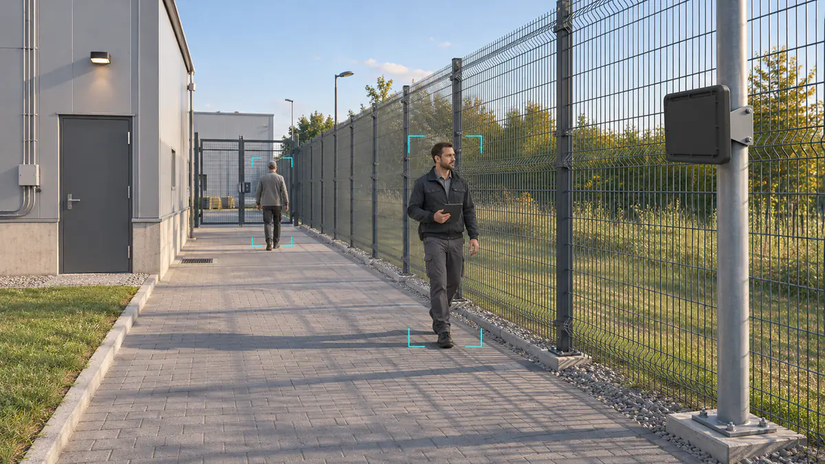
For a long, clear boundary, assess a pole position that looks along the inspection strip rather than pointing directly at the nearest fence panel. The intended walking route should remain within the useful detection sector through the part of the site where a warning is required.
Inspect the site from the candidate mounting position, not only from ground level beside it. Check the fence-side edge, the interior-side edge, access doors, parked equipment, vegetation and any posts or cabinets in front of the radar. A clear centreline does not prove that both edges are covered.
Do not use a drawing of a wide sector as evidence that the entire strip will be detected uniformly. The relationship between range, direction, target movement and installation geometry needs to be verified. Likewise, a quoted antenna beamwidth is not automatically the usable detection width for every target and distance.
Choose a stable support with a clear view from the front of the sensor. Check the arrangement with a gate open and closed, and with vehicles or movable equipment in the positions normally used on site. A layout that works only when a loading bay is empty leaves an operational gap.
If a required path falls outside the observation from one end, evaluate a changed pole position or another observation point. First improve the view; increasing sensitivity cannot guarantee detection behind a solid obstruction.
3. Treat a building corner as a separate observation problem
A radar covering one side of a solid building should not be assumed to cover the return path around its corner. Draw a direct line from the proposed sensor position to each required part of the route. If that line passes through the building, the route needs another usable viewpoint.
A bend in a mesh fence is not identical to a solid building corner. Inspect what actually blocks or reflects the signal, including fence posts, opaque panels, vegetation and nearby structures. Test both directions through the turn because the target’s position relative to those objects changes during the passage.
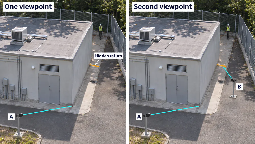
Inspect the return from a viewpoint with a clear line of sight. The lines identify viewing directions; detector coverage must be checked on site.
In the comparison, viewpoint A looks along the near side of the building. The return needs to be evaluated from a position such as B with a direct view of that path. The sight lines identify the viewpoints to inspect; actual detector coverage still requires a field check.
Axis also identifies radar shadows behind solid obstructions in its installation considerations. This is a useful site-planning principle. Mounting dimensions, tilt recommendations and multi-device limits must come from the documentation for the radar being installed.
For an L-shaped perimeter, evaluate each leg and the transition between them. If one position cannot observe both legs at the required warning location, plan an additional viewpoint. Making the alarm polygon extend around the corner does not create a view through the structure.
4. Check the ground near the pole before choosing the height
The ground immediately below or beside a mounted radar can fall outside its useful observation geometry. A close-distance figure on a specification sheet does not, by itself, demonstrate coverage of the ground directly underneath the pole.
Check the close route first, then the far route. Identify whether a person can enter the required alarm strip close to the mounting point without already passing through a visible part of the monitored area. That path must be included in the acceptance walk.
Mounting higher may improve the view over some obstructions, but it changes the near-ground view and aiming requirements. Tilting farther down may improve one close area while changing the useful view farther away. Use the model’s installation instructions and site geometry to choose height and tilt, then test both ends of the required strip.
For an MSR-S200 perimeter radar, the published detection-distance interval is 1–200 m. Treat it as an initial specification, not proof that a particular elevated installation covers every ground position between those distances. Confirm the intended mounting arrangement with the technical team and include the pole-adjacent route in the field check.
If the near route remains unobservable, move the pole, change the monitored strip or provide another observation point or suitable sensor. Do not accept an untested patch beside the equipment simply because the far end detects well.
5. How many radars does a fence line need?
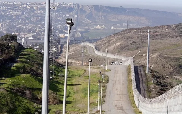
Do not divide total fence length by maximum detection range to obtain a final radar quantity. Maximum range does not account for corners, blocked views, near-ground gaps, strip width or the point where the project needs an alarm.
Use this sequence to build the initial layout:
- Split the perimeter at meaningful changes. Mark corners, buildings, gates, elevation changes and regular vehicle-parking areas.
- Assign a candidate viewpoint to each required route. Check that it can see the relevant strip and the warning location.
- Mark unproven areas. Include close to each pole, both strip edges, behind obstructions and where two observation areas meet.
- Test or review those areas before fixing the quantity. Revise pole positions or add observation points where a required route remains uncovered.
| Perimeter layout | Initial planning approach | What must be verified |
|---|---|---|
| One clear straight strip | Evaluate a position looking along the required route | Near and far limits, both edges and actual warning locations |
| A return around a solid building | Assess separate viewpoints for the two sides | The hidden return and the transition through the corner |
| A strip interrupted by parked trucks or equipment | Consider a different pole position or additional observation | Coverage with normal obstructions present |
| Two adjacent radar areas | Define and walk the joining area | No required route through a gap; correct platform handling of both streams |
For a multi-radar layout, confirm coexistence and configuration requirements for the exact devices and firmware. There is no universal spacing or overlap percentage that can be applied to every radar. A plan to add a second sensor also needs confirmation that the devices can operate together in the proposed arrangement.
Two radars may assign different IDs to the same person. Do not assume automatic cross-device handover or one shared identity. The receiving system must handle observations and alarm events appropriately. The radar object-tracking guide explains why a track ID and a persistent identity are different concepts.
6. Keep the detection footprint and platform alarm zone separate
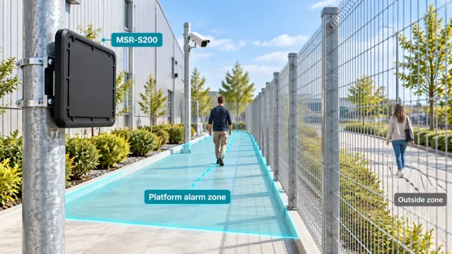
A radar may observe a person outside the required alarm area. That can be a valid observation even though the security platform should not raise an intrusion alarm for that location. Conversely, drawing an alarm zone on a map does not establish that the radar can observe every point inside it.
For MSR-S200 integration, radar target data are sent over Ethernet using TCP. The connected security platform uses those data for the required zone rules and camera coordination. Confirm the actual platform features rather than assuming that the radar itself provides every alarm or camera-control function.
Align the map with the real site before refining the zone boundary. If all tracks are displaced or rotated, inspect the installation coordinates and map calibration. Moving the alarm polygon to compensate for a misaligned map can hide the problem at one point while creating it elsewhere.
After placement and mapping are correct, check the rule at gates, authorised routes and the public-side boundary. If unnecessary events remain, follow the perimeter radar false-alarm troubleshooting workflow while retesting the required detection after each change.
7. Walk the routes that can reveal a coverage gap
Use an authorised tester and keep a reference record of each route. Walk along the boundary in both directions, across the required strip, near the pole and through corners and joins. Looking at a moving dot somewhere on the map is not enough to confirm that the important entry paths are protected.
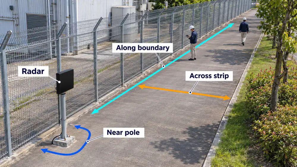
Walk along the boundary, across the required strip and near the pole; add routes through corners and between observation areas.
| Walk-test route | What to check | Useful evidence |
|---|---|---|
| Along the fence in both directions | Observation through the required section and correct track position | Route markers, reference video, timestamps and target records |
| Across the strip at near and far locations | Detection and the required alarm before the agreed boundary or response point | First usable observation, actual alarm time and tester location |
| Beside and around the pole | Any accessible close route that bypasses the observed area | The path taken and any missing interval |
| Through a corner, obstruction or radar-area join | Interruption, recovery and platform event handling | Both device streams where applicable, the full passage and resulting alarms |
Record the first usable observation and the alarm as separate events. The radar may start tracking before a platform rule is satisfied. For a warning requirement, verify that the alarm is available by the agreed location, including the delays introduced by processing and any persistence rule.
If the source radar record is correct but the map or alarm is wrong, inspect the receiving platform and calibration. If the required route is absent from the source record, return to the view, geometry, configuration and observation conditions. Repeating the same route helps show whether a change actually corrected the problem.
Repeat relevant checks with normal gate positions and routine obstructions present. Retest after moving the sensor, changing its aim or modifying the alarm rule. Agree the tested conditions and acceptance limits in advance, and retain difficult passages as well as successful ones.
8. Prepare a placement plan that can be reviewed and installed
Before requesting a quantity or pole recommendation, provide:
- A marked plan: fence or wall layout, the protected side, strip width and required warning positions.
- Candidate mounting points: proposed heights, aiming directions and photographs looking along each required route.
- Obstructions and moving structures: buildings, vegetation, gates, vehicle parking and changes in ground level.
- Required outcomes: target display, zone alarm, camera cueing or another platform action, with the required timing.
- Installation constraints: available power, network connections, access and any other radars nearby.
The WaveLogic perimeter security solution combines radar target information with the connected platform’s verification and response workflow. For an MSR-S200 layout review, send the perimeter plan and proposed mounting views so the team can assess the observation points and integration requirements.
A useful placement plan identifies where each required route is observed, how the near and hidden areas are covered, and how the result will be checked on site. Confirm those details before turning nominal range into a final equipment quantity.