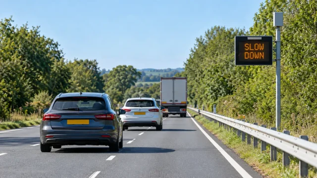
Radar speed signs measure the speed of an approaching vehicle and provide immediate visual feedback to the driver. They are also known as driver feedback signs, vehicle-activated speed displays or dynamic speed display signs.
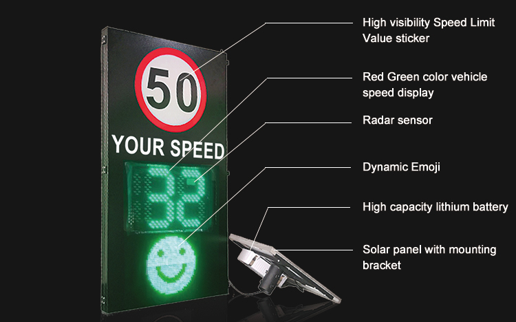
A typical sign displays the approaching vehicle’s speed beside a static speed-limit sign. Depending on the controller settings, it may remain blank below a threshold, display the measured speed, show a warning message or activate additional warning devices.
This guide explains how radar speed signs work, how the radar sensor communicates with the display and what system integrators should consider when selecting and installing the equipment.
What is a radar speed sign?
A radar speed sign is a traffic-calming device made up of a speed-measuring sensor, a display and a controller. The radar measures an approaching vehicle, and the controller determines what information the sign should show.
The display may provide:
- The vehicle’s measured speed;
- A message such as “SLOW DOWN” or “TOO FAST”;
- A comparison with the posted speed limit;
- A warning beacon or other vehicle-activated indication;
- No display when a vehicle is outside the configured conditions.
Radar speed signs are intended primarily to influence driver behaviour through immediate feedback. They should not automatically be described as enforcement systems.
Radar speed signs and speed enforcement are different
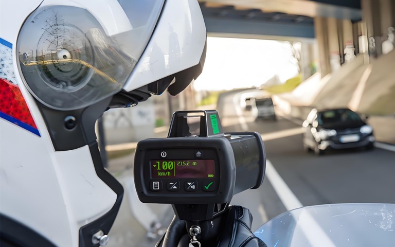
A feedback sign tells a driver how fast the vehicle is travelling and encourages voluntary speed reduction. It normally does not identify the vehicle or issue a violation record.
An enforcement system may require:
- A jurisdiction-approved speed-measurement method;
- Vehicle and number-plate images;
- Reliable association between the measured speed and the correct vehicle;
- Evidence timestamps and site information;
- Calibration records and periodic verification;
- Compliance with local legal and operating requirements.
A radar speed sign may be installed near enforcement activity, but the sign itself should not be treated as legal evidence unless the complete system has been designed and approved for that purpose.
Main components of a radar speed sign
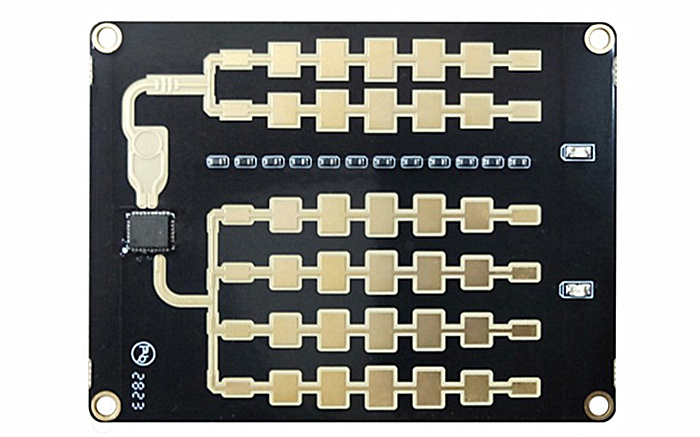
Radar speed sensor
The radar detects an approaching or receding vehicle and reports its speed. The required outputs depend on the sign controller, but may include speed, direction, target presence and sensor status.
Display and static sign
The electronic display shows the measured speed or a configured message. It is often installed with a conventional speed-limit sign so that the driver can compare the posted limit with the displayed vehicle speed.
Sign controller
The controller receives speed data from the radar and applies display rules. It may control:
- The minimum speed at which the display activates;
- The threshold for a warning message;
- The maximum speed value that can be displayed;
- Flashing or beacon behaviour where permitted;
- Display brightness;
- Data logging and communications.
Power supply
A radar speed sign may use grid power, a battery, solar charging or a combination of power sources. Power design should account for the radar, controller, display brightness, communications equipment, seasonal sunlight and local temperature.
Communications and data storage
Some systems operate independently. Others provide local or remote access for configuration, status monitoring and traffic-data retrieval.
The communication method can include a wired serial interface, Ethernet, cellular connection or another manufacturer-specific interface. Compatibility should be verified before the system is assembled.
How the radar measures vehicle speed
Many feedback signs use Doppler radar. The radar transmits radio-frequency energy toward the road and receives reflections from moving vehicles.
Motion causes a frequency shift in the reflected signal. The radar processes this Doppler shift to determine the radial component of the vehicle’s speed.
In simplified form:
Measured radial speed = vehicle speed × cos(mounting angle)
If the radar beam is not aligned with the vehicle’s direction of travel, the measured radial speed is lower than the vehicle’s actual road speed. The mounting angle must therefore follow the radar manufacturer’s requirements.
Approaching and receding vehicles
Some installations need to measure only approaching vehicles because the sign faces oncoming traffic. Direction filtering helps prevent vehicles travelling away from the sign or moving on another carriageway from activating the display.
Before selecting the radar, confirm whether it can report approaching, receding or bidirectional traffic and whether the controller can use that direction information.
Single-target and multi-target conditions
A feedback sign usually needs to display one speed value at a time. The site can nevertheless contain several vehicles inside the radar beam.
The system designer should understand how the radar selects the reported target. Possible selection rules include the nearest vehicle, the strongest return, the fastest vehicle or a vehicle inside a defined detection area.
Closely spaced or side-by-side traffic can make a simple single-value output more difficult to interpret. Testing should include realistic traffic rather than only one isolated vehicle.
From radar detection to driver feedback
A typical operating sequence is:
- A vehicle enters the radar detection area.
- The radar detects its direction and speed.
- The radar sends the result to the sign controller.
- The controller compares the speed with configured thresholds.
- The controller selects the appropriate display state.
- The sign shows the speed or warning for the configured period.
- The display resets when the vehicle leaves or a new target is selected.
The response should be quick enough for the driver to see and understand the message while there is still time to reduce speed before reaching the relevant location.
Display thresholds and operating logic
Activation threshold
The display does not always need to activate for every detected vehicle. A lower activation threshold can reduce unnecessary display changes and reserve the sign’s attention for vehicles approaching or exceeding the relevant speed.
Warning threshold
The controller can change the display behaviour when the measured speed passes a configured threshold. The exact rule should follow the traffic authority’s policy and local sign regulations.
Maximum displayed speed
Some agencies limit or suppress unusually high displayed values so that drivers are not encouraged to compete for the highest number. Above the configured limit, the sign may show a warning message or another permitted display state instead of the actual speed.
Display duration
If the display changes too quickly between vehicles, the message can become confusing. If it holds one value for too long, the next driver may see the previous vehicle’s speed.
The controller should balance response time, hold time and target-selection behaviour for the expected traffic flow.
Where radar speed signs are used
School zones
Feedback signs can draw attention to a lower speed environment near schools. Scheduled operation may be coordinated with school-zone hours or warning beacons where regulations allow.
Road curves
A sign can be installed before a curve to show the approaching vehicle’s speed or activate a warning when the configured threshold is exceeded.
FHWA evaluations have studied dynamic speed feedback signs at rural curves and found that results vary by site. Placement, visibility, road geometry and the driver’s perception of the hazard all affect performance.
Work zones
Portable signs can provide immediate speed feedback where traffic patterns or speed limits change temporarily. The equipment must be placed where it remains visible without creating an additional roadside hazard.
Residential and transition areas
Feedback signs may be used where vehicles enter a lower-speed area from a faster road. The transition should give drivers sufficient distance to perceive the message and adjust speed safely.
Industrial sites and private roads
Factories, logistics centres, ports and campuses can use radar feedback displays to remind drivers of internal speed policies. These installations still require suitable placement, sight distance and traffic-direction filtering.
Choosing a radar sensor for a speed sign
A radar should be selected according to the complete sign workflow rather than one headline specification.
| Requirement | Question to confirm |
|---|---|
| Direction | Must the system detect approaching vehicles, receding vehicles or both? |
| Detection area | Can the radar cover the required road area without activating from unwanted lanes? |
| Speed output | What units, resolution and update interval does the controller require? |
| Target selection | How does the radar behave when several vehicles are present? |
| Interface | Can the controller receive the radar’s electrical and data interface? |
| Response time | Will the displayed result reach the driver at the correct position? |
| Environment | Does the installation meet power, enclosure, temperature and mounting requirements? |
| Diagnostics | Can the controller determine whether the radar is operating normally? |
Installation geometry
Radar orientation
The radar should face the intended traffic stream with the specified horizontal and vertical orientation. A large angle between the beam and vehicle travel direction can introduce cosine error.
Sign visibility
The driver must have enough sight distance to notice the sign, read the display and respond. Vegetation, other signs, road curvature, parked vehicles and roadside structures can block visibility.
Detection position
The radar should detect the vehicle early enough to produce useful feedback but not so far away that vehicles on another road or lane activate the display.
Detection distance alone does not determine good performance. The beam footprint, mounting position, road width, lane layout and surrounding traffic matter as well.
Roadside safety
The sign, pole, trailer, solar panel and battery enclosure must be installed according to the applicable roadside safety and traffic-control requirements. Portable equipment should not obstruct traffic, pedestrians or visibility.
Commissioning and verification
After installation, test the complete sign rather than checking only whether the display illuminates.
A commissioning test should include:
- Approaching vehicles at several representative speeds;
- Vehicles travelling in the opposite direction;
- Adjacent-lane and side-road traffic;
- Closely spaced vehicles;
- Large and small vehicles;
- The lower activation threshold;
- The warning and maximum-display thresholds;
- Nighttime display visibility;
- Power and charging behaviour;
- Communication and data logging, when enabled.
The displayed speed should be compared with an appropriate reference method. Any formal calibration requirements depend on the application and local regulations.
Traffic data and evaluation
Some sign controllers store anonymous speed and traffic information. Possible records include:
- Timestamped vehicle speeds;
- Vehicle counts;
- Speed distributions;
- Configured threshold exceedances;
- Operating and power status.
Where data logging is available, agencies can compare conditions before and after installation. Useful measures include mean speed, 85th-percentile speed and the proportion of vehicles exceeding a defined threshold.
A reduction observed directly at the sign should not automatically be assumed to continue far downstream. Evaluation location and duration should be documented.
Common installation mistakes
- Excessive radar angle: causes the displayed result to differ from road speed;
- Detection zone too wide: allows vehicles on another lane or road to activate the sign;
- Sign positioned too late: gives drivers insufficient time to respond before the hazard;
- Unclear target-selection logic: produces confusing values in multi-vehicle traffic;
- No maximum display rule: may encourage drivers to test unusually high displayed speeds;
- Inadequate power design: causes reduced availability or display brightness;
- No post-installation verification: allows alignment or threshold errors to remain undetected;
- Treating feedback as enforcement: confuses a traffic-calming display with an approved evidence system.
Radar speed sign sensor integration
WaveLogic provides radar sensing components for integration into driver-feedback displays and roadside warning controllers. The display, enclosure, power system and sign controller form part of the integrator’s complete product.
The HC-TR20 radar speed sensor is designed for vehicle speed detection and roadside feedback or warning applications. It can provide speed information to a compatible controller without requiring pavement installation.
Before integration, confirm the required direction, detection area, interface, speed units, update behaviour and controller logic.
For applications requiring individual target position and multi-lane tracking rather than a single feedback speed, see the HC-M150 multi-lane traffic radar.
Frequently asked questions
What are radar speed signs called?
Common terms include radar speed sign, speed feedback sign, driver feedback sign, vehicle-activated speed display and dynamic speed display sign.
Do radar speed signs issue tickets?
A normal feedback sign displays speed or a warning but does not issue a violation. Enforcement requires additional equipment, evidence handling and any approvals required by the local jurisdiction.
Can a radar speed sign collect traffic data?
Some sign controllers can store anonymous speeds, counts and threshold events. This depends on the controller and communications configuration rather than the radar sensor alone.
Why does the displayed speed differ from another measuring device?
Possible causes include mounting angle, different measurement positions, target selection, rounding, update timing or incorrect configuration. The complete installation should be checked against a suitable reference.
Can one radar speed sign cover multiple lanes?
A radar may detect vehicles in more than one lane, but displaying one unambiguous speed becomes difficult when several vehicles approach together. Site testing and clearly defined target-selection behaviour are necessary.
Do radar speed signs work at night?
Radar speed measurement does not rely on visible light. The display must still provide suitable nighttime brightness without excessive glare, according to applicable sign requirements.
Are radar speed signs effective?
Research summarized by NHTSA and FHWA indicates that speed feedback displays can reduce vehicle speeds at suitable locations. Results vary with placement, road environment, sign operation and whether drivers perceive a reason to slow down.
Conclusion
Radar speed signs provide immediate, non-punitive feedback by measuring an approaching vehicle and displaying its speed or a configured warning.
Good performance depends on more than the radar’s nominal detection range. Direction filtering, mounting angle, target selection, threshold logic, sign visibility and response distance all affect the driver’s experience.
System integrators should test the complete sign under realistic traffic conditions and distinguish clearly between driver feedback, traffic-data collection and legal enforcement.