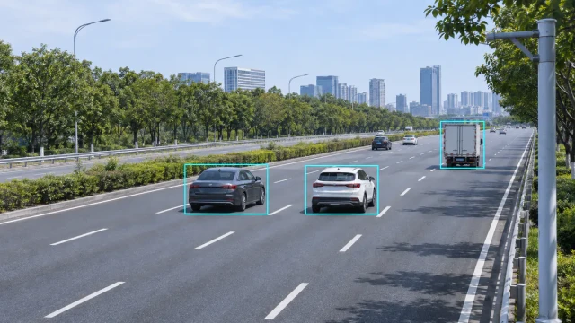
3D traffic radar provides target-level information about vehicles moving through a roadway detection area. Instead of reporting only that a vehicle has passed, a target-tracking radar can supply position, radial speed, movement direction and trajectory data for each detected object.
This information can support traffic-flow monitoring, signal control, queue detection, camera triggering and speed-enforcement integration. However, the term “3D radar” is not used consistently by every manufacturer. System integrators should therefore examine the actual output data and measurement capabilities rather than selecting a sensor from the dimension stated in its name.
What Is 3D Traffic Radar?
In the conventional radar definition, a 3D radar measures target range, azimuth and elevation. These three spatial measurements locate a target in three-dimensional space.
Roadside traffic-radar terminology can be less consistent. Some products described as 3D traffic radar output longitudinal position, lateral position and radial velocity. Others provide range, horizontal angle, speed and a tracked vehicle ID without measuring elevation.
For an ITS project, the important questions are:
- Which coordinates does the radar output?
- Does it report individual targets or only traffic statistics?
- Can it assign vehicles to lanes?
- Does it maintain a stable target ID and trajectory?
- Can it detect slow or stopped vehicles?
- What is the target update rate and communication latency?
For a detailed explanation of spatial radar terminology, see 3D Radar Explained: How It Works and What It Measures.
How 3D Traffic Radar Detects Vehicles
A traffic radar transmits radio-frequency signals toward the roadway and processes the echoes reflected from vehicles and other objects. Depending on its waveform and antenna architecture, the radar can estimate several target parameters.
Range
Range is the distance between the radar and the reflecting target. FMCW radar commonly estimates range from the frequency difference between the transmitted chirp and the delayed received signal.
Radial velocity
The Doppler effect provides the component of vehicle velocity directed toward or away from the radar. This is radial velocity, not automatically the vehicle’s full road speed.
Azimuth angle
Multiple receiving antenna channels can estimate the horizontal arrival angle of the reflected signal. Combining range and azimuth allows the processor to calculate longitudinal and lateral target position.
Elevation angle
A radar with sufficient vertical antenna aperture may also estimate elevation. Many roadside traffic applications do not require precise target height, so elevation capability must be confirmed from the product’s actual output specification.
Target tracking
Tracking algorithms associate detections across consecutive frames. The radar can then maintain a target ID, estimate trajectory and reduce fluctuations in measured position and speed.
From Radar Detection to ITS Data
The radar signal-processing chain normally produces individual detections before creating a usable traffic target list. A typical process includes:
- Transmit a radar waveform into the road scene.
- Receive reflections from vehicles and surrounding objects.
- Estimate range and Doppler velocity.
- Estimate arrival angle using multiple antenna channels.
- Detect significant targets above the noise and clutter level.
- Group related detections into vehicle targets.
- Associate targets across successive measurement frames.
- Assign vehicles to lanes or configured detection zones.
- Output target data and calculated traffic statistics.
The final target list may contain fields such as:
- Target ID
- Longitudinal distance
- Lateral position
- Radial or compensated vehicle speed
- Movement direction
- Lane number
- Target length or classification
- Trajectory and tracking status
- Detection confidence
Not every radar supplies all these fields. Output definitions, coordinate systems and update rates must be checked before system integration.
Target-Level Data and Traffic Statistics
Target-level data describes each detected vehicle. Traffic statistics summarize vehicle activity over a defined time interval.
A traffic-radar system may calculate:
- Vehicle count by lane
- Average speed
- Lane occupancy
- Time headway
- Space headway
- Vehicle classification
- Queue length
- Wrong-way events
Traffic-management platforms may only need aggregated statistics every 30 seconds, one minute or five minutes. A camera-control or enforcement system may instead require low-latency target coordinates for every radar frame.
The receiving system should therefore define whether it needs target data, event messages, statistical records or a combination of all three.
3D Traffic Radar Applications
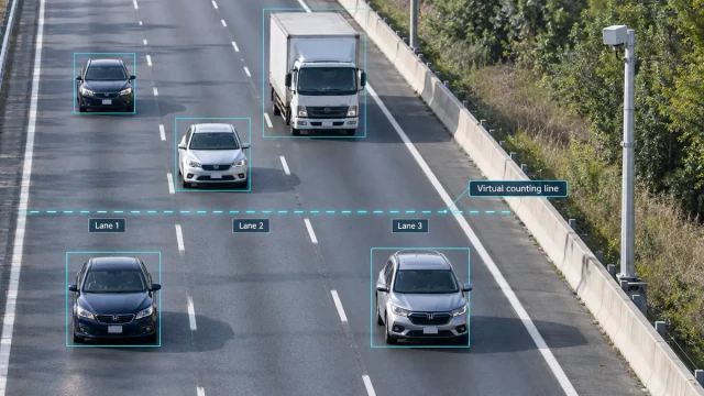
Multi-lane traffic-flow monitoring
A roadside radar can track vehicles across several lanes and calculate lane-level volume, speed, occupancy and headway. Unlike an in-road inductive loop, an above-ground radar can normally be installed without cutting the pavement.
The radar’s field of view must cover the required road width while maintaining sufficient separation between adjacent vehicles and lanes.
Intersection monitoring and signal control
Radar can provide vehicle presence, approach speed, queue information and configurable detection-zone events to a traffic-signal controller.
Stopped-vehicle detection depends on the waveform and signal-processing design. A simple CW Doppler radar generally detects movement but cannot maintain the presence of a stationary vehicle. A product described as “3D” does not automatically guarantee reliable stopped-target detection.
Queue and congestion detection
Tracked vehicle positions and speeds can be used to identify slow-moving traffic and estimate the upstream end of a queue. A system can then provide congestion data, trigger warnings or support dynamic traffic management.
Camera triggering
Radar coordinates can direct a camera toward a selected vehicle or trigger image capture when a target crosses a virtual line. Reliable operation requires synchronization between radar data, camera latency and the physical measurement zone.
Speed-enforcement integration
For enforcement integration, radar must associate measured speed and position with the correct vehicle and image. This becomes more difficult when several vehicles travel closely together across multiple lanes.
A complete system must preserve the relationship between the radar target, measurement location, trigger event and captured evidence. See the speed enforcement integration solution for the system-level workflow.
Wrong-way and incident detection
Movement direction and trajectory data can identify vehicles travelling against the permitted direction. Abnormal stopping, sudden speed reduction and unexpected trajectories may also support incident-detection logic.
Radar data alone should not be treated as a complete incident decision in every application. Many systems combine radar events with camera verification or traffic-management rules.
Side-Fire and Forward-Looking Installation
Side-fire installation
A side-mounted radar observes vehicles across the roadway. This arrangement can allow one sensor to cover multiple lanes and is commonly used for traffic statistics.
Possible challenges include:
- Occlusion of small vehicles by trucks
- Reduced separation between closely spaced targets
- Barriers or vegetation obstructing the field of view
- Difficulty assigning vehicles during lane changes
- Lower measured radial speed at large observation angles
Forward-looking installation
A forward-looking radar points generally along the vehicle travel direction. This geometry can provide a stronger radial-speed component and longer observation time for approaching vehicles.
Forward-looking radar is often suitable for target tracking, speed measurement, camera triggering and advance detection. Road curvature and vertical road profile must still be included in the installation design.
Radial Speed and Installation Angle
Radar directly measures the velocity component along its line of sight. When the vehicle direction forms an angle θ with the radar beam, the measured radial component is:
vr = v cos(θ)
If the installation angle is not considered, the measured radial speed can be lower than the vehicle’s actual road speed. Some traffic radars compensate for this using target position and a calibrated road coordinate system.
Accurate alignment is particularly important for speed-enforcement and lane-level applications. Mounting height, horizontal angle, sensor position and road direction should be measured rather than estimated visually.
3D Traffic Radar Compared with Other Detectors
| Technology | Main strengths | Important limitations |
|---|---|---|
| Traffic radar | Direct speed measurement, target tracking, multi-lane coverage and above-ground installation | Requires correct alignment and may experience occlusion or multipath |
| Inductive loop | Established lane presence and counting performance | Requires pavement installation and road work for repair |
| Video detection | Provides visual verification and flexible image-based analytics | Performance can be affected by lighting, visibility and lens contamination |
| LiDAR | Dense spatial measurements and precise object outlines | Optical performance can be affected by severe visibility conditions and sensor contamination |
No detector technology is best for every site. Radar and video are often combined because radar supplies target distance and speed while the camera provides visual context.
Important Selection Criteria
When evaluating a 3D traffic radar, system integrators should compare:
- Required detection distance and road width
- Forward-looking or side-fire installation
- Number of monitored lanes
- Range and angular resolution
- Speed range and speed accuracy
- Stationary-target detection capability
- Maximum simultaneous target count
- Target update rate and output latency
- Lane assignment and classification capability
- Communication interface and message protocol
- Environmental protection and operating conditions
- Configuration, diagnostics and firmware management
A maximum-range value alone does not demonstrate suitability. The radar must detect the required target type with adequate accuracy and update rate under the project’s actual geometry and traffic density.
Site Validation
Radar performance should be verified after installation using synchronized reference data. Depending on the application, acceptance testing may compare:
- Vehicle counts by lane
- Measured speed against a calibrated reference
- Lane-assignment accuracy
- Target-position error
- Detection probability
- False-target rate
- Queue-length estimation
- Event and camera-trigger timing
Testing should include normal flow, congestion, lane changes, large trucks and low-traffic conditions. A short test involving only free-flowing passenger cars may not reveal the problems that occur in a dense multi-lane scene.
WaveLogic 3D Traffic Target Data
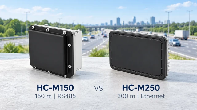
The WaveLogic HC-M250 traffic radar is designed for long-range, multi-lane vehicle detection and target tracking. It provides vehicle target information for traffic monitoring, road coordination and system-integration applications.
System integrators can use radar target data to build lane-level statistics, event rules and camera-control workflows. The exact implementation should be based on the required coordinates, communication protocol, update rate and acceptance criteria.
See the traffic flow monitoring solution for an overview of how target-level radar data is converted into operational traffic information.
Frequently Asked Questions
Does 3D traffic radar always measure elevation?
No. In conventional radar terminology, a 3D radar measures range, azimuth and elevation. In the traffic-sensor market, some products use “3D” for other combinations of position and velocity data. The actual output fields must be verified.
Can 3D traffic radar identify individual vehicles?
A target-tracking radar can assign temporary target IDs and follow vehicles through its detection area. These IDs are radar tracks and should not be confused with permanent vehicle identity or license-plate recognition.
Can traffic radar detect stopped vehicles?
Some FMCW and target-tracking radar systems can detect stationary vehicles. Basic CW Doppler sensors generally require movement. Stopped-target capability depends on the waveform and processing design, not simply on the term “3D.”
Can one radar monitor several lanes?
Yes, provided its field of view, detection distance, angular resolution and target capacity suit the road geometry. The number of usable lanes should be validated at the intended mounting position.
Is 3D traffic radar suitable for speed enforcement?
It can provide the speed, position and trajectory information required by an enforcement system. The complete system must still ensure target-to-image association, calibration, event timing and compliance with applicable approval requirements.
Conclusion
3D traffic radar allows an ITS platform to work with individual vehicle targets instead of only simple passage pulses. Position, speed, lane and trajectory data can support traffic statistics, signal control, queue monitoring, camera triggering and enforcement integration.
The label “3D” alone is not a sufficient specification. Successful deployment depends on the radar’s real output fields, detection geometry, stopped-target performance, interface compatibility and site validation.