A traffic speed sensor measures the speed of vehicles travelling through a defined road area. Depending on the sensing method, it may also report vehicle presence, direction, range, lane position, coordinates or trajectory data.
In this article, “speed sensor” refers to a roadside traffic sensor—not the wheel-speed, transmission or ABS sensors installed inside a vehicle. Roadside speed sensors are used in traffic monitoring, speed feedback signs, warning systems, camera triggering and enforcement-related applications.
What is a traffic speed sensor?
A traffic speed sensor observes vehicles from a fixed roadside, overhead or median-mounted position. It estimates vehicle speed from a measurable change over time, such as:
- Doppler frequency shift measured by radar;
- Travel time between two detection points;
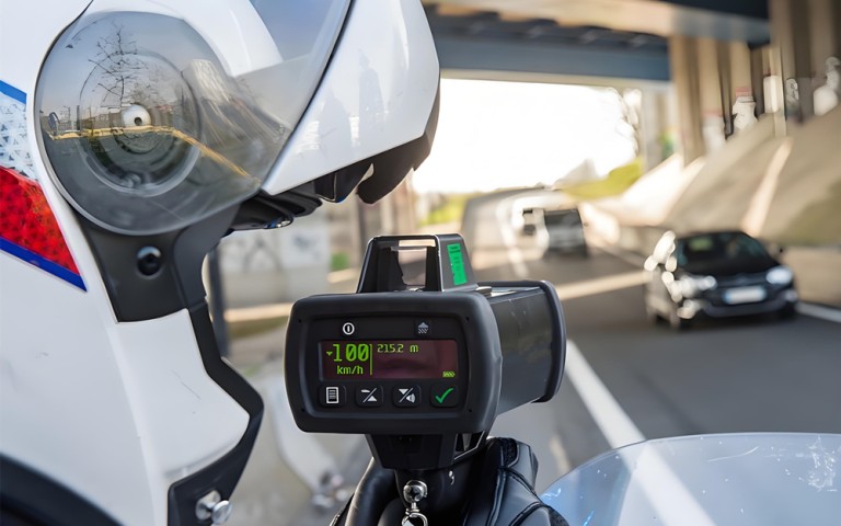
- Change in target range measured by radar or lidar;
- Vehicle displacement between calibrated video frames;
- Sequential activation of pavement-mounted detectors.
The appropriate method depends on whether the system needs only a single speed value or must also distinguish lanes, track multiple vehicles and associate each speed measurement with the correct target.
Spot speed and average speed are different measurements
Spot speed
Spot speed is the speed of a vehicle at or near a defined measurement position. Radar, lidar, video analytics and paired inductive loops can all be used for spot-speed measurement.
This measurement is commonly used by speed feedback displays, traffic monitoring stations, roadside warning systems and enforcement-camera workflows.
Average or section speed
Average speed is calculated from the time a vehicle takes to travel between two separated points. The system must identify the same vehicle at both locations and divide the known travel distance by the elapsed time.
A radar unit installed at one location normally provides spot speed rather than average speed over a long road section.
Main traffic speed-sensing technologies
1. Doppler radar speed sensors
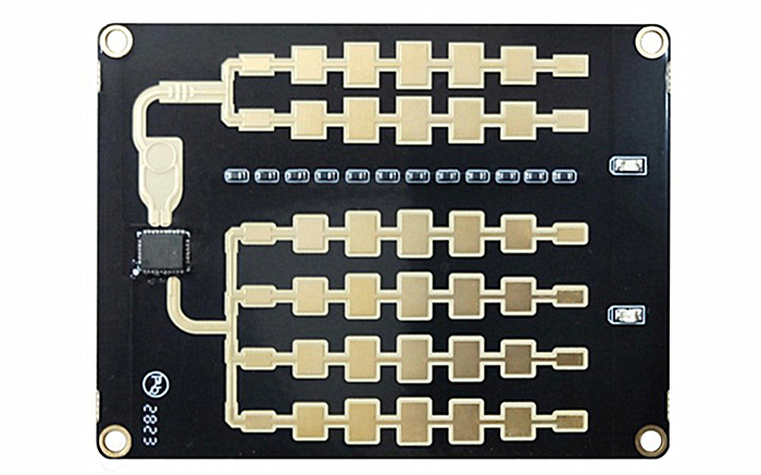
Doppler radar transmits radio-frequency energy toward the road. Energy reflected from a moving vehicle returns with a frequency shift related to the vehicle’s radial velocity relative to the radar.
Continuous-wave radar can provide direct speed measurement with fast response and no pavement cutting. It is widely used for speed displays, traffic surveys and vehicle-triggered warning systems.
However, a basic continuous-wave radar generally cannot measure the range of a stationary target. Its ability to distinguish multiple vehicles also depends on the antenna design and signal-processing method.
2. FMCW and tracking radar
Frequency-modulated continuous-wave radar processes changes in the transmitted frequency to estimate target range. When combined with Doppler processing and tracking algorithms, it can provide speed, range, direction and position information for individual targets.
This is useful on multi-lane roads where a system must determine which vehicle generated a measurement. A tracking radar can maintain separate target records rather than outputting only the strongest detected speed.
For traffic enforcement integration, target association is often as important as the speed value itself. The controller or camera system must receive enough information to link a speed event with the correct vehicle and lane.
3. Paired inductive-loop detectors
Inductive loops are installed in or beneath the road surface. A vehicle changes the electrical characteristics of the loop as it passes over it.
A single loop primarily detects presence or passage. Speed can be estimated using two detection points separated by a known distance:
Speed = distance between detectors ÷ travel time
Loop systems can provide repeatable results when correctly installed and maintained. Their main disadvantage is the need to cut or access the pavement, which can increase installation effort and maintenance disruption.
4. Lidar speed measurement
Lidar emits narrow optical pulses and measures the return time from a target. Repeated distance measurements allow the system to calculate the target’s change in range and therefore its speed.
The narrow beam can help an operator or fixed system select a specific vehicle. Performance depends on alignment, line of sight, target reflectivity and environmental visibility.
5. Video-based speed measurement
A video system estimates speed by tracking a vehicle’s movement across a calibrated image. The relationship between image coordinates and real-world road distance must be established accurately.
Video can combine classification, plate capture and visual evidence in one system. Its speed result may nevertheless be affected by camera vibration, calibration errors, shadows, poor lighting, weather and vehicle occlusion.
Comparison of common speed-sensor methods
| Technology | Measurement principle | Main advantages | Key considerations |
|---|---|---|---|
| Doppler radar | Frequency shift from a moving target | Direct speed measurement, fast response, non-intrusive installation | Mounting angle and multi-target separation |
| FMCW tracking radar | Range and Doppler processing | Speed, range, position and multi-target tracking | Lane mapping, installation geometry and data integration |
| Paired loops | Travel time over a known distance | Established measurement method and clear detection points | Pavement installation and maintenance |
| Lidar | Change in optical range over time | Narrow target-selection area | Alignment, line of sight and visibility |
| Video | Movement through a calibrated image | Combines traffic data with visual information | Calibration, lighting, occlusion and camera stability |
How radar calculates vehicle speed
A radar sensor measures the component of vehicle velocity directed toward or away from the sensor. If the radar beam is aligned directly with the direction of travel, the measured radial velocity is close to the vehicle’s actual road speed.
When the radar is mounted at an angle, the measured value is affected by the cosine of that angle. In simplified form:
Measured speed = actual speed × cos(mounting angle)
An incorrectly configured angle generally makes the displayed speed lower than the vehicle’s actual speed. Mounting geometry must therefore be considered during installation and commissioning.
Single-target measurement and multi-target tracking
A basic speed sensor may work well when one vehicle occupies the detection area at a time. Multi-lane roads create a more difficult problem because several vehicles can be present simultaneously at different ranges and speeds.
A multi-target traffic radar should be able to:
- Separate detections by range and angle;
- Maintain a track for each detected vehicle;
- Assign vehicles to lanes or measurement zones;
- Report direction, speed and position for each target;
- Maintain target identity long enough for downstream association;
- Generate a trigger only when the configured conditions are met.
The system integrator should confirm how the radar handles adjacent vehicles, overtaking, lane changes and partially occluded targets.
What determines speed-measurement quality?
A percentage alone does not fully describe sensor performance. A technical evaluation should distinguish between the following characteristics:
- Error: the difference between the reported and reference speed;
- Resolution: the smallest speed increment represented by the output;
- Repeatability: the consistency of repeated measurements under similar conditions;
- Update rate: how often the sensor provides a new result;
- Detection probability: the proportion of relevant vehicles successfully measured;
- Target association: whether the reported speed belongs to the correct vehicle;
- Latency: the delay between measurement and data output or trigger generation.
A sensor can report a precise-looking number but still produce an incorrect result if it is associated with the wrong lane or vehicle. Multi-target applications must evaluate both speed error and target-association performance.
Installation factors that affect results
Mounting angle and orientation
The horizontal and vertical mounting angles influence the measured radial speed and detection footprint. The installation should follow the sensor’s specified geometry rather than relying only on visual alignment.
Detection-zone location
The measurement zone should be placed where vehicles are visible to the sensor and where the speed value serves the intended function. A zone located directly after a sharp curve, stop line or merge may observe vehicles that are actively accelerating or braking.
Occlusion
Large trucks can hide smaller vehicles from a roadside sensor. Overhead mounting or a more suitable viewing angle may reduce this effect, but the selected arrangement must be evaluated for the actual road layout.
Road curvature and gradients
Curves and slopes change the relationship between the sensor beam and vehicle direction. A configuration suitable for a straight, level road should not automatically be applied to a curved or graded section.
Environmental conditions
Lighting strongly affects camera systems, while optical sensors depend on visibility and line of sight. Radar is not dependent on ambient light, but installation, multipath reflections and surrounding structures still require attention.
Outputs and system integration
Before selecting a traffic speed sensor, determine what information the receiving system actually needs. Possible outputs include:
- Vehicle speed and direction;
- Presence or passage event;
- Target range and position;
- Lane or measurement-zone identifier;
- Vehicle count or classification;
- Track coordinates and trajectory;
- Timestamp or trigger event;
- Sensor status and diagnostic information.
Interfaces may include serial communication, Ethernet, discrete trigger signals or a manufacturer-specific data protocol. Compatibility should be confirmed using the product interface documentation before the controller, display or camera workflow is designed.
Typical applications
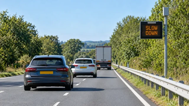
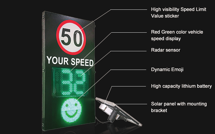
Speed feedback signs
A compact Doppler radar can detect an approaching vehicle and send its measured speed to a roadside display or controller. The system may change the displayed message when a configured speed threshold is exceeded.
The HC-TR20 radar speed sensor is intended for applications such as speed feedback displays, vehicle-triggered warnings and related roadside control systems.
Traffic monitoring
Speed data can be combined with vehicle count, lane flow, occupancy and headway information. A multi-target radar is preferable when the monitoring system requires individual vehicle tracks or reliable separation across several lanes.
Camera and enforcement integration
A camera workflow requires more than a general speed reading. The radar must identify the relevant target, determine when it crosses the configured measurement or trigger position and provide sufficient data for association with the captured image.
The HC-M150 traffic radar provides target-level data for multi-lane traffic-system integration. See the speed enforcement radar solution for an overview of measurement-line events and camera/controller integration.
Curve and variable-speed warnings
A speed sensor can activate a warning sign when an approaching vehicle exceeds a configured threshold. The trigger logic should account for the sensor location, warning distance, road geometry and the time required for a driver to respond.
How to choose a traffic speed sensor
Use the following questions when comparing sensors:
- Is the application monitoring, feedback, warning or enforcement-related?
- Does the system require only speed, or also range, lane and target coordinates?
- How many lanes and simultaneous vehicles must be handled?
- Must the sensor measure approaching traffic, receding traffic or both?
- Where can the sensor be mounted, and what viewing angle is available?
- What speed range, update rate and response time are required?
- How will the result be transferred to the display, controller or camera?
- Does the application require formal calibration or legal type approval?
- How will installation performance be verified against a reference?
Frequently asked questions
Is a traffic speed sensor the same as a vehicle wheel-speed sensor?
No. A wheel-speed sensor is installed on a vehicle and supports systems such as ABS and stability control. A traffic speed sensor is installed beside or above a road and measures passing vehicles externally.
Can one radar measure several vehicles at the same time?
A multi-target tracking radar can measure and track several vehicles, but capability depends on its antenna, signal processing, field of view and output protocol. A basic Doppler module may report only one dominant speed value.
Does radar angle affect the reported speed?
Yes. Radar measures radial velocity. If the mounting angle is not handled correctly, cosine error can cause the reported speed to be lower than the actual road speed.
Can radar detect a stopped vehicle?
A basic continuous-wave Doppler radar relies on target motion and normally does not provide range to a stationary target. FMCW radar can measure range and can support stationary-target detection depending on its design and configuration.
Is a camera more accurate than radar?
Neither technology is automatically more accurate in every installation. Radar performance depends on geometry and target association; video performance depends on camera calibration, stability, visibility and tracking quality. The complete system should be verified under representative road conditions.
Can any speed sensor be used for legal enforcement?
No. Legal enforcement requirements depend on the country or jurisdiction. The complete measuring system may need certification, calibration, evidence handling and periodic verification. A component’s technical speed output does not by itself establish legal approval.
Conclusion
Traffic speed can be measured using radar, paired loops, lidar or calibrated video. The best choice depends on the number of lanes, target density, installation environment and the data required by the receiving system.
For a simple warning display, a compact Doppler radar may provide the necessary speed and direction information. For multi-lane monitoring or camera integration, range, position, lane assignment and target tracking become equally important. Evaluating the complete measurement and association process produces a more reliable system than comparing only a headline accuracy figure.