Inductive loop detectors and radar are two widely used technologies for detecting vehicles and collecting traffic data. Both can support traffic signal control, road monitoring and intelligent transportation systems, but their installation methods, data outputs and maintenance requirements are very different.
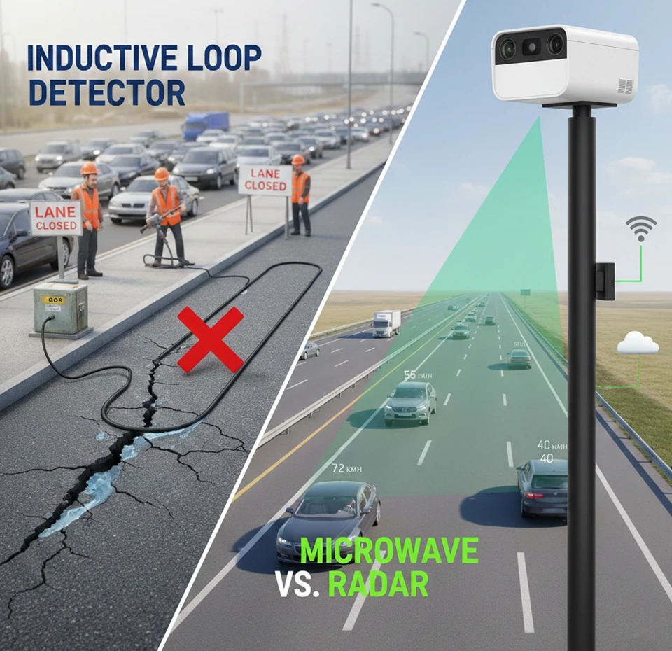
An inductive loop is embedded in the pavement and provides reliable detection at a defined point. Radar is installed above or beside the road and can observe a larger detection area without cutting the pavement.
The decision is not simply whether radar is newer than loop technology. A correctly installed loop remains effective for many presence-detection applications. Radar becomes more attractive when a project requires speed, multiple detection zones, multi-lane coverage or reduced disruption to the road surface.
This guide compares loop detectors vs radar from an engineering and system-integration perspective.
What Is an Inductive Loop Detector?
An inductive loop detector consists of insulated wire installed in a cut or preformed section of the pavement. The loop is connected through a lead-in cable to an electronic detector unit in the traffic controller cabinet.
The detector electronics energise the loop and monitor its electrical characteristics. When a vehicle containing conductive metal enters the loop’s detection area, it changes the loop inductance. The detector recognises this change and reports vehicle presence or passage.
A loop detector system generally includes:
- Loop wire embedded in the pavement
- Sealant protecting the saw cut
- Lead-in wire and cable
- Roadside pull box or junction
- Detector electronics
- Traffic controller input
The loop geometry determines the detection area. A vehicle outside that physical area cannot be detected without installing another loop.
What Data Can an Inductive Loop Provide?
A single inductive loop can normally provide:
- Vehicle presence
- Vehicle passage
- Traffic count
- Lane occupancy
- Basic gap information
- A controller call for signal actuation
A pair of loops separated by a known distance can provide additional information such as:
- Vehicle speed
- Direction
- Approximate vehicle length
- Basic classification
The data available therefore depends on the number and arrangement of loops. A single presence loop at a stop line is not equivalent to a dual-loop speed-measurement station.
Loops are especially effective when the application requires a binary answer at a fixed point: is a vehicle present in this detection zone?
What Is a Radar Traffic Detector?
A radar traffic detector transmits radio waves toward the road and analyses signals reflected from vehicles.
Depending on the radar design, it may measure:
- Vehicle presence
- Vehicle speed
- Range
- Direction
- Lane position
- Coordinates
- Target trajectory
- Vehicle count
- Occupancy
- Headway
- Queue length
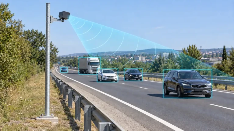
Radar is installed on a pole, gantry, mast arm, median or roadside structure. Because the sensor is not embedded in the pavement, detection zones can often be adjusted through configuration rather than road reconstruction.
However, not every traffic radar provides the same data.
A basic CW Doppler sensor may measure only moving-target speed and direction. An FMCW presence or tracking radar can measure range and may detect both moving and stationary vehicles.
For a detailed explanation of radar types and outputs, see our guide to radar traffic detectors.
Loop Detector vs Radar Comparison
| Factor | Inductive loop detector | Radar traffic detector |
|---|---|---|
| Installation | Embedded in pavement | Mounted above or beside the road |
| Pavement cutting | Normally required | Not required for the sensor |
| Detection area | Defined by physical loop geometry | Defined by beam coverage and software zones |
| Vehicle presence | Strong point-presence detection | Supported by suitable FMCW or presence radar |
| Vehicle speed | Usually requires two loops | Direct Doppler speed measurement |
| Multi-lane coverage | Normally separate loops for each lane or zone | One radar may cover several lanes |
| Target coordinates | Not normally available | Available from tracking radar |
| Stationary vehicles | Yes in presence mode | Depends on radar waveform and processing |
| Road resurfacing | May damage or require replacement | Sensor remains above the pavement but may require recalibration |
| Maintenance access | Requires work in or near traffic lanes | Often accessible from pole or roadside position |
| Visual evidence | No | No |
| Configuration changes | May require new pavement work | Detection zones may be reconfigured in software |
| Main strength | Reliable fixed-zone presence | Speed, coverage and richer target data |
The table describes general characteristics. Actual performance depends on product design, installation and site conditions.
Installation Requirements
Loop detector installation
Installing an inductive loop normally requires:
- Marking the loop geometry on the pavement.
- Closing or controlling the affected traffic lane.
- Cutting slots in the road surface.
- Installing loop wire.
- Routing the lead-in cable.
- Sealing the saw cuts.
- Connecting the detector electronics.
- Testing sensitivity and presence behaviour.
Installation quality directly affects reliability. Damaged insulation, poor joints, water intrusion, incorrect sealant or pavement movement may cause intermittent operation or failure.
A newly paved road may be suitable for installing loops during construction. Retrofitting loops into an operating road can involve more disruption and traffic-control cost.
Radar installation
Installing radar normally requires:
- Selecting a pole, mast arm or gantry position.
- Providing power and communication.
- Mounting and aiming the radar.
- Configuring lanes and detection zones.
- Connecting the controller or management platform.
- Validating detection under real traffic.
Radar avoids saw cutting but introduces its own engineering requirements. Mounting height, viewing angle, road curvature, large-vehicle occlusion and reflective roadside structures can affect performance.
Non-intrusive does not mean installation-free. A radar must still be correctly positioned, configured and tested.
Vehicle Presence and Stop-Line Detection
Inductive loops are well established for stop-line presence detection.
A loop installed at the stop bar can maintain a controller call while a vehicle remains above it. This direct relationship between the physical detection zone and controller input is easy to understand and troubleshoot.
Radar can also provide stop-line presence, but only when the radar supports stationary-target or presence detection.
A basic Doppler speed sensor should not be used as a stopped-vehicle detector. When a vehicle stops, its Doppler frequency approaches zero and may be removed with stationary background reflections.
An FMCW presence radar can use range information and configured zones to maintain vehicle presence. Its performance should be tested for:
- Small vehicles
- Motorcycles
- Vehicles stopping near zone boundaries
- Queues extending between zones
- Large vehicles hiding smaller vehicles
- Vehicles remaining stationary for extended periods
For a simple stop-line call, a loop may remain an appropriate solution. Radar becomes more valuable when several approach zones, queue measurements or target trajectories are also required.
Speed Measurement
Radar has a clear functional advantage when individual vehicle speed is required.
Doppler radar measures the radial component of vehicle speed from the frequency shift of the reflected radio signal. This can provide speed from one above-road sensor.
Read our Doppler radar guide for an explanation of radial velocity and installation angle.
A single loop does not directly provide speed. A dual-loop installation can estimate speed by measuring the time a vehicle takes to travel between two known detection zones.
Dual-loop speed performance depends on:
- Accurate loop spacing
- Correct pairing of loop events
- Vehicle acceleration between loops
- Simultaneous vehicles
- Detector timing resolution
- Controller processing
For applications centred on speed measurement, radar generally requires less pavement infrastructure and provides more flexible target data.
Multi-Lane Coverage
Loops are normally installed separately for each lane and detection location. A four-lane road requiring stop-line and advance detection may therefore need several physical loops.
Radar can cover a wider road area from one mounting position, provided its field of view, angular resolution and processing capacity support the road geometry.
One radar may create multiple virtual zones or maintain individual vehicle tracks across several lanes.
Usable lane coverage depends on:
- Number and width of lanes
- Radar mounting position
- Horizontal field of view
- Angular resolution
- Road curvature
- Traffic density
- Large-vehicle occlusion
- Required target accuracy
A claim that one radar covers multiple lanes should be validated at lane boundaries and under dense traffic, not only with isolated vehicles.
Traffic Data Output
Loops and radar can both provide traffic statistics, but they obtain them differently.
Loop-based statistics
A loop system may calculate:
- Volume from passage events
- Occupancy from detection duration
- Speed from paired loops
- Approximate length from speed and occupancy
- Lane-by-lane counts
The data is associated with the fixed physical position of each loop.
Radar-based statistics
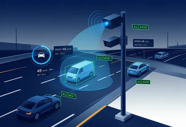
Tracking radar may calculate statistics from individual target tracks:
- Vehicle count
- Individual speed
- Average lane speed
- Lane occupancy
- Time headway
- Gap
- Queue length
- Vehicle direction
- Target coordinates
- Trajectory
Buyers should confirm whether the radar itself produces statistical reports or only outputs target records for an external processor.
For a broader comparison of sensor technologies, see our traffic flow sensors guide.
Maintenance and Road Lifecycle
Loop maintenance
Loop reliability can be affected by:
- Pavement cracking
- Road movement
- Water intrusion
- Failed wire insulation
- Damaged lead-in cables
- Utility construction
- Milling and resurfacing
- Poor saw-cut sealing
- Lightning and electrical interference
Repair may require lane closure and pavement work. When a road is resurfaced, existing loops may need to be protected, reinstalled or replaced.
Radar maintenance
Radar is not embedded in the road, so pavement deterioration does not directly break the sensor wiring.
Maintenance may include:
- Checking mounting stability
- Inspecting the enclosure
- Confirming alignment
- Cleaning the radome when necessary
- Verifying power and communication
- Reviewing diagnostic data
- Recalibrating zones after road changes
- Updating firmware under controlled procedures
Radar can reduce work in live traffic lanes, but poles, cables, surge protection and network equipment still require maintenance.
Initial Cost vs Lifecycle Cost
A simple comparison of sensor purchase prices is misleading.
Loop detector cost should include:
- Loop wire and detector electronics
- Saw-cutting labour
- Lane closure and traffic management
- Sealant and pavement restoration
- Lead-in cabling
- Controller input hardware
- Future repair
- Replacement during resurfacing
Radar cost should include:
- Radar hardware
- Pole or gantry structure
- Mounting brackets
- Power supply
- Communication equipment
- Integration software
- Configuration
- Field commissioning
- Future calibration and maintenance
Loops may offer a low hardware cost where pavement work is already included in a new construction project. Radar may provide a lower-disruption alternative for an operating road or a project requiring several lanes and detection zones.
The correct comparison is total installed and lifecycle cost—not loop wire versus radar hardware.
Reliability and Environmental Factors
Loops and radar fail in different ways.
An inductive loop is not affected by visibility, shadows or fog because it is located in the pavement. Its main vulnerabilities are pavement condition, cable integrity and electrical installation.
Radar does not depend on visible light and generally operates across day and night. However, its performance can be affected by:
- Incorrect mounting angle
- Partial occlusion
- Multipath reflections
- Large metal structures
- Strong stationary clutter
- Radome contamination
- Extreme precipitation
- Movement of the mounting structure
Neither technology should be described as universally maintenance-free or 100% accurate. Reliability depends on correct design and site-specific validation.
Radar Occlusion
Occlusion occurs when a large vehicle blocks the radar’s view of another vehicle.
It can be more significant when radar is mounted low at the roadside and looks across several lanes. A truck in the nearest lane may hide a smaller vehicle in a farther lane.
Possible mitigation measures include:
- Increasing mounting height
- Selecting a different viewing angle
- Using an overhead position
- Adding another sensor
- Reducing the covered road width
- Adjusting tracking parameters
Loops do not experience optical or radar line-of-sight occlusion because each loop detects vehicles directly above its physical location.
This can make loops attractive for high-confidence point detection in individual lanes.
Detection Zones and Future Road Changes
A physical loop cannot be moved through software. Changing the detection location normally requires a new loop or additional pavement work.
Radar detection zones can often be changed in software. This is useful when:
- Lane markings change
- Signal-control strategy changes
- Advance detection distance changes
- A new queue zone is required
- The same radar is reused for a different event
However, software flexibility has limits. The new zone must remain inside the radar’s measurable field of view, and road geometry changes may require physical realignment and recommissioning.
Controller Integration
Loop detector integration
Loop detector electronics commonly provide familiar controller inputs such as presence or pulse outputs.
This can simplify replacement within an established signal cabinet. Traffic technicians may already understand the wiring, sensitivity settings and fault behaviour.
Radar integration
Radar may connect through:
- Relay or contact outputs
- Serial communication
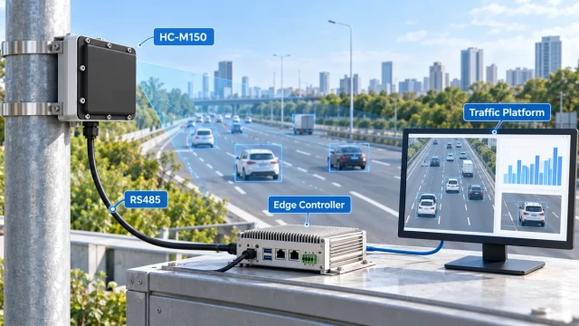
- RS485
- Ethernet
- Vendor protocol
- Standardised controller messages
A radar may need an interface module to convert virtual detection zones into controller calls.
Before selecting radar, confirm:
- Required controller input
- Message format
- Lane and zone numbering
- Update rate
- Communication latency
- Failure-state behaviour
- Device health messages
- Recovery after network interruption
A radar that detects vehicles correctly but cannot provide the required controller output is not a complete replacement for a loop system.
Replacing Existing Loops with Radar
Replacing loops should begin with a functional survey rather than a one-for-one hardware substitution.
Step 1: Document the current loop functions
Identify which loops provide:
- Stop-line presence
- Advance detection
- Queue detection
- Speed estimation
- Gap measurement
- Turning movement count
- Signal priority input
Step 2: Define the required radar outputs
Determine whether the replacement radar must provide:
- Virtual presence zones
- Target-level tracks
- Speed
- Queue length
- Direction
- Lane assignment
- Contact closures
- Network messages
Step 3: Check the mounting geometry
Confirm that the radar can see every required lane and zone without unacceptable occlusion.
Step 4: Plan controller integration
Map each radar output or virtual zone to the appropriate controller input or software function.
Step 5: Run parallel validation
Where possible, compare the radar against the existing loops before removing them.
Test:
- Vehicle calls by lane
- Presence duration
- Missed and false calls
- Motorcycles
- Large trucks
- Dense queues
- Lane-boundary behaviour
- Communication interruption
Step 6: Document acceptance criteria
Define the required performance for each function instead of relying on one general accuracy percentage.
When Should You Choose Inductive Loops?
Loops may be appropriate when:
- Reliable point presence at a fixed location is the main requirement.
- The road is already being constructed or resurfaced.
- The controller uses established loop inputs.
- Lane-by-lane detection zones are simple and permanent.
- Suitable overhead or roadside mounting positions are unavailable.
- Radar occlusion cannot be resolved.
- Existing maintenance capability strongly supports loop technology.
When Should You Choose Radar?
Radar may be appropriate when:
- Pavement cutting should be avoided.
- The road must remain open during installation.
- Multiple lanes or detection zones are required.
- Individual vehicle speed is required.
- Target coordinates or trajectories are needed.
- Queue length or advance detection must cover a long area.
- Detection zones may need future adjustment.
- Road resurfacing is frequent.
- The traffic system needs richer data than a binary controller call.
For projects requiring multi-lane vehicle coordinates, speed and traffic statistics, the HC-M150 multi-lane traffic radar can provide target-level data for external controllers and traffic platforms.
Can Radar and Loops Be Used Together?
Yes. Hybrid systems can use each technology for the function it performs best.
Examples include:
- Loops for stop-line presence and radar for advance speed detection
- Radar for multi-lane tracking and loops as a confirmation source
- Loops for permanent signal actuation and radar for temporary queue monitoring
- Radar during road construction while existing loops are unavailable
Using two technologies increases hardware and integration complexity, so the second sensor should support a defined operational or verification requirement.
Frequently Asked Questions
Is radar always better than an inductive loop?
No. Radar provides richer data and non-intrusive installation, but loops remain effective for reliable detection at a fixed pavement location.
Can radar detect vehicles stopped at a red light?
A suitable FMCW presence or tracking radar can detect stopped vehicles. A basic CW Doppler speed sensor generally cannot.
Can one radar replace several loops?
Potentially. One radar may provide several virtual zones or monitor multiple lanes. The replacement must be validated for each original loop function.
Can a single loop measure speed?
A single loop normally provides presence, passage and occupancy. Speed generally requires paired loops or another measurement method.
Do radar detectors work in bad weather?
Radar does not depend on visible illumination and generally operates through common roadside weather. Heavy precipitation, radome contamination and installation conditions can still affect performance.
Does radar require lane closures?
Mounting and commissioning may require local traffic control, but the sensor itself normally does not require saw cutting across the lane.
Which technology has lower maintenance?
The answer depends on the road, installation and maintenance organisation. Radar avoids pavement-related loop failures, while loops avoid radar alignment, networking and line-of-sight issues.
Should old loops be removed after installing radar?
Not immediately. Run a defined comparison period when practical, verify every required function and confirm controller behaviour before decommissioning the old system.
Conclusion
Inductive loop detectors and radar solve different traffic-detection problems.
Loops provide dependable vehicle presence at fixed pavement locations and integrate easily with established signal-controller equipment. Their limitations are intrusive installation, fixed detection geometry and exposure to pavement damage.
Radar avoids pavement cutting and can provide vehicle speed, multiple detection zones, multi-lane coverage and target-level traffic data. Its performance depends on mounting geometry, field of view, target processing and system integration.
Choose loops when simple, permanent point detection is the main requirement. Choose radar when the project requires non-intrusive installation, richer vehicle data or flexible road coverage.
The final decision should be based on required outputs, installation constraints and lifecycle costs—not on the assumption that one technology is always superior.