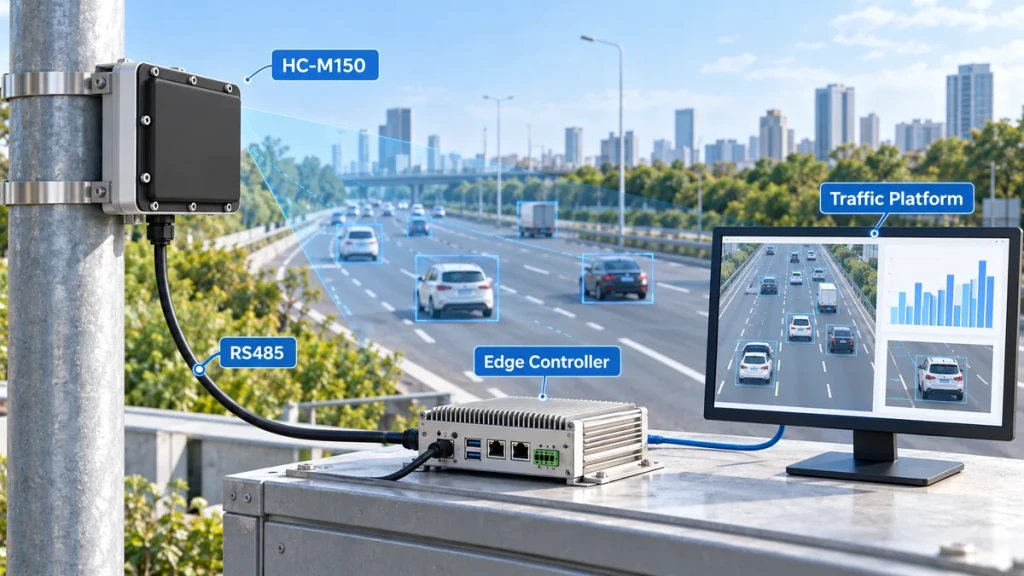
The HC-M150 connects to a host controller through RS485 and supplies both vehicle-level tracking data and traffic statistics. A successful integration requires more than receiving serial data: the controller must distinguish individual vehicle tracks, measurement-line states and completed statistical intervals.
For example, a vehicle can appear in many successive tracking updates while passing through the detection area. Those updates describe the same tracked vehicle. They must not be counted as separate vehicles.
This guide explains how to build an HC-M150 traffic radar integration around the data your application actually needs. Detailed communication specifications are available separately from our technical team.
1. Choose the data your application needs
Start with the required output, rather than attempting to use every available data item.
For a traffic-counting dashboard, begin with lane-level statistical results. For a live vehicle display, use target tracking data. For a roadside warning function, combine the relevant target or measurement-line information with the controller’s application rules.
| Application | Recommended starting data | What the receiving system should do |
|---|---|---|
| Traffic volume monitoring | Periodic vehicle counts and lane statistics | Store results against the correct lane, measurement line and interval |
| Live vehicle visualization | Target ID, position and velocity | Update existing tracks as new observations arrive |
| Measurement-line presence monitoring | Real-time presence states | Interpret the state at the configured lane and line |
| Wrong-way warning | Wrong-way states and supporting target information | Apply event rules and validate the intended traffic direction |
| Radar-assisted camera integration | Target position, velocity and timing information | Associate the correct vehicle with the camera workflow |
These are application choices, not interchangeable outputs. A target list is not a completed traffic count, and a presence state is not a permanent record that a vehicle has passed.
2. Connect the radar to an RS485 host
The HC-M150 multi-lane traffic radar uses RS485 communication at 115200 baud and a 12 V DC power supply.
A typical development setup connects the radar to an RS485-to-USB adapter and a computer. An installed system can instead use an industrial controller or edge computer with a suitable RS485 interface.
Check the delivered unit’s wiring documentation before making connections. Confirm the power supply, signal connections and remaining serial-port settings against the documentation supplied for that device version.
RS485 describes the electrical interface. It does not, by itself, mean that a device uses Modbus or directly supplies JSON, HTTP or Ethernet messages. Select the receiving hardware and software around the radar’s documented communication format.
First establish reliable reception on one radar. Verify stable communication before adding platform forwarding, visualization or camera-control functions.
If the final application needs an IP connection, an appropriate controller or gateway can receive the RS485 data and translate decoded information into the platform’s required format. That translation belongs to the integration system; it should not be assumed to be a native radar output.
3. Keep tracking, real-time states and interval statistics separate
The most important software design decision is to handle these data groups separately.
Vehicle tracking data
Tracking data describes individual detected targets. It includes target identification, X/Y position, X/Y velocity and target-length information.
Use the target ID to update the corresponding active track as new observations arrive. Do not create a new vehicle record for every update of the same ID.
An ID identifies a radar track, not a licence plate or a permanent vehicle identity. The receiving application should manage track expiry and must not assume that an ID identifies the same physical vehicle indefinitely or across separate radar devices.
X/Y coordinates also require interpretation. They are not automatically longitude and latitude. Confirm the coordinate origin, axis directions and installed alignment before drawing targets on a road layout or mapping them into another system.
The velocity components must use the same coordinate convention. Do not treat one component as the vehicle’s road-direction speed without confirming the geometry. A negative component can indicate travel direction rather than invalid data.
Real-time measurement-line states
Real-time traffic information includes presence and wrong-way states associated with configured lanes and measurement lines.
These states describe conditions at a measurement location. They should not be interpreted as the occupancy of an entire road section.
For a warning application, the receiving controller should use the state together with appropriate event logic. For example, it may need to distinguish an ongoing condition from a new event so that the same condition does not repeatedly create duplicate alarms.
Periodic traffic statistics
Periodic statistics describe vehicle passages during a configured collection interval.
Available statistical information includes:
- Vehicle count.
- Time occupancy.
- Average speed.
- 85th-percentile speed.
- Time headway.
- Time gap.
Keep the associated lane, measurement line, vehicle category where applicable, and statistical interval with each result.
Do not combine results from different measurement lines as though they represented different vehicles. The same vehicle may cross more than one line.
4. Do not confuse the 50 ms update with the statistical interval
HC-M150 supports a nominal 50 ms tracking update, equivalent to up to 20 updates per second. This supports continuous observation of target movement.
The statistical collection interval serves a different purpose.
For example, a system may receive frequent target updates while collecting traffic statistics over a 60-second interval. The frequent updates describe movement; the completed interval describes traffic measured over that minute.
A vehicle visible for approximately two seconds may appear in around 40 successive tracking updates. Counting those observations would greatly overstate traffic volume.
For a standard counting application, use the configured measurement-line statistics. If the host application performs its own counting from trajectories, it needs explicit line-crossing, direction and duplicate-prevention logic.
When storing interval statistics, use the interval and measurement location to identify the result. Repeated delivery of the same result must not create duplicate totals.
5. Configure lanes and measurement lines before validating statistics
Receiving correctly decoded data does not prove that the road has been configured correctly.
Before comparing traffic counts, complete the installation alignment, lane boundaries, measurement lines and intended detection area.
The HC-M150 installation guide explains the physical mounting and configuration sequence.
For the first integration test, use one clearly observed lane, one measurement line and a simple collection interval, such as 60 seconds.
Observe a short sequence of vehicle passages and check:
- Vehicles are assigned to the intended lane.
- The measurement line lies within a reliably observed area.
- The configured direction matches actual vehicle movement.
- The completed statistical count corresponds to passages through that line.
- The receiving application stores the result once, against the correct interval.
Then extend the test to the remaining lanes and required measurement lines.
This approach helps separate three different problems: communication errors, road-configuration errors and application-processing errors.
For a broader deployment, see the traffic flow monitoring solution.
6. Interpret occupancy, headway and time gap correctly
Traffic statistics can be received successfully but still be used incorrectly.
Time occupancy describes the proportion of a statistical interval during which vehicles occupy the configured measurement location. It is not the percentage of the full detection area covered by vehicles.
Time headway describes the time separation between the fronts of successive vehicles passing a measurement location.
Time gap describes the separation between the rear of one vehicle and the front of the following vehicle.
Headway and gap are therefore different measurements. They should not share the same database label or be substituted for one another in a dashboard.
The 85th-percentile speed is also different from average speed. It represents the speed at or below which 85 percent of the relevant vehicle observations fall; it is not 85 percent of the average speed.
Preserve these distinctions when mapping radar outputs to platform fields. A convenient platform label should not change the meaning of the original measurement.
7. Handle timing, missing data and restarts explicitly
Use available timing, sequence and status information to monitor the data stream. Record host reception time separately from device-provided timing information.
Do not assume that a radar timing value is an absolute UTC timestamp suitable for matching camera images without additional synchronization.
The receiving application should distinguish:
- A valid observation with no detected targets.
- A completed statistical interval with zero vehicle passages.
- Missing or invalid communication.
- A device restart or a newly established connection.
These conditions should not all produce the same zero-filled record.
For example, a communication outage is not evidence that the road was empty. Mark the affected interval as incomplete or unavailable according to the platform’s data-quality policy.
Use a bounded receive buffer, reject incomplete or invalid messages according to the supplied communication documentation, and allow the receiver to recover after interrupted communication. Do not assume that one serial-port read corresponds to one complete radar message.
For camera integration, verify timing and vehicle association at the actual measurement area. A working RS485 connection alone does not establish correct image-to-vehicle matching. See the speed enforcement integration solution for the wider system workflow.
8. Troubleshoot the integration in a fixed order
| Symptom | Check first |
|---|---|
| No incoming data | Power, wiring, adapter operation, selected port and documented serial settings |
| Data is received but cannot be interpreted | Correct device documentation, receiver buffering and message validation |
| Tracks appear rotated or displaced | Installation alignment, coordinate convention and the application’s coordinate transformation |
| Vehicle counts are much higher than observed | Repeated tracking updates counted as vehicles, repeated statistical records, or totals combined across measurement lines |
| One direction is absent | Detection-area settings, direction filtering and velocity interpretation |
| Statistics appear under the wrong lane | Configured lane numbering and the host application’s lane mapping |
| Data gaps appear as zero traffic | Missing-data handling and communication-quality flags |
| Camera images show the wrong vehicle | Timing, target association and the relationship between the measurement location and camera view |
Troubleshoot from the connection outward: communication first, decoded data second, road configuration third and application logic last.
Changing every setting at once makes it difficult to identify which part of the integration is responsible.
9. What should the first successful integration demonstrate?
Before connecting the radar to the final platform, aim to demonstrate a small, complete workflow:
- Receive a stable RS485 data stream.
- Display a passing vehicle as one continuously updated track.
- Confirm its position and direction against the road.
- Receive a completed statistical interval for the intended lane and measurement line.
- Compare the count with observed vehicle passages.
- Disconnect and reconnect communication, confirming that the application reports the interruption and resumes correctly.
After this workflow is reliable, add platform forwarding, additional lanes, longer-term storage and application-specific events.
This creates a usable integration in stages without confusing transport, radar configuration and business logic.
Get HC-M150 integration support
For an HC-M150 integration project, provide your host hardware, required connection method, lane layout, desired data outputs and intended application.
Specify whether you need individual vehicle tracks, measurement-line states, periodic traffic statistics or a combination of these outputs.
Our technical team can provide the appropriate communication documentation and help confirm the data mapping for your system. Visit the HC-M150 product page to discuss your integration requirements.