If radar detects a person but the PTZ camera points beside them, falls behind or loses them when zooming, start by identifying which part of the result is wrong. Check the radar position, the commanded camera direction and the displayed video against the same person and time. A correct radar track does not automatically establish correct camera pointing.
A useful first sequence is to check pointing at known positions with a wide camera view, repeat at near and far positions, and then test walking targets. Only after those checks should you assess tighter zoom and multi-target switching. This separates geometry, timing and selection problems so that each adjustment has a clear purpose.
1. Match the symptom to the first check
Record the problem before changing the configuration. Keep a reference view of the test person, the radar target record, the selected target ID where available, and a PTZ video recording. Include the camera and radar locations, current calibration, zoom state and which application controls the camera.
| Observed symptom | First check | Useful distinction |
|---|---|---|
| The camera points in the wrong direction at several known positions | Radar/map alignment, camera position and coordinate conversion | A wrong source position versus a wrong conversion from position to camera direction |
| Near positions align but distant positions do not | Calibration coverage, orientation error and site elevation | A local calibration fit versus a fit across the required area |
| Known-position checks work but walking targets lag | Data age, command handling, PTZ response and video delay | Physical pointing lag versus an old video image |
| The person is visible at wide view but lost after zooming | Pointing error, zoom policy, focus and movement margin | Incorrect direction versus a field of view that is too tight |
| The camera jumps between people | Selected-target changes, priority and competing camera controllers | A selection decision versus unstable pointing toward one selected target |
For the broader division of responsibilities, see how security radar detection and integration work. The camera-control application needs to interpret the observations and issue suitable commands; each stage should be checked against the actual site.
2. If the camera points the wrong way, verify the coordinates first
First establish whether the radar position is correct on the site map. Compare a person at several known locations with the displayed position. Look for a consistent rotation, displacement, mirrored movement or a wrong scale. Check axis directions, units, radar orientation and the map’s alignment with the ground.
If the radar position is wrong, correct that relationship before changing the PTZ calibration. Moving a camera preset until one person appears centred can hide the source error at one location while leaving other positions incorrect.
If the mapped position is correct, inspect the camera location used by the control application. A camera and radar on the same pole still have different optical and sensor positions. Separate poles require their actual locations to be represented; mounting them near each other does not make their coordinate origins identical.
Then verify the conversion into camera pan and tilt: reference direction, offsets, mounting height and the application’s ground or elevation model. Check the camera model and supported command method too. A successful network connection or manual pan command does not prove that position-based pointing has been calibrated.
Also confirm which controller has authority. A patrol, operator, camera-side tracker and radar-control application can issue competing commands. Use the site’s supported test procedure to isolate the intended controller, then verify how normal operator override and return-to-service behaviour work.
3. If near points work and far points miss, expand the calibration check
Do not accept a calibration because one nearby point looks right. Check positions across the actual monitoring area, including near and far routes and both lateral edges. A small directional error can become a significant displacement at distance.
Use clearly identifiable reference positions and the calibration method supported by the actual platform. Record camera and radar mounting information consistently. If ground level changes, check whether the application’s model accounts for it; a flat-ground assumption can produce vertical pointing errors on a slope.
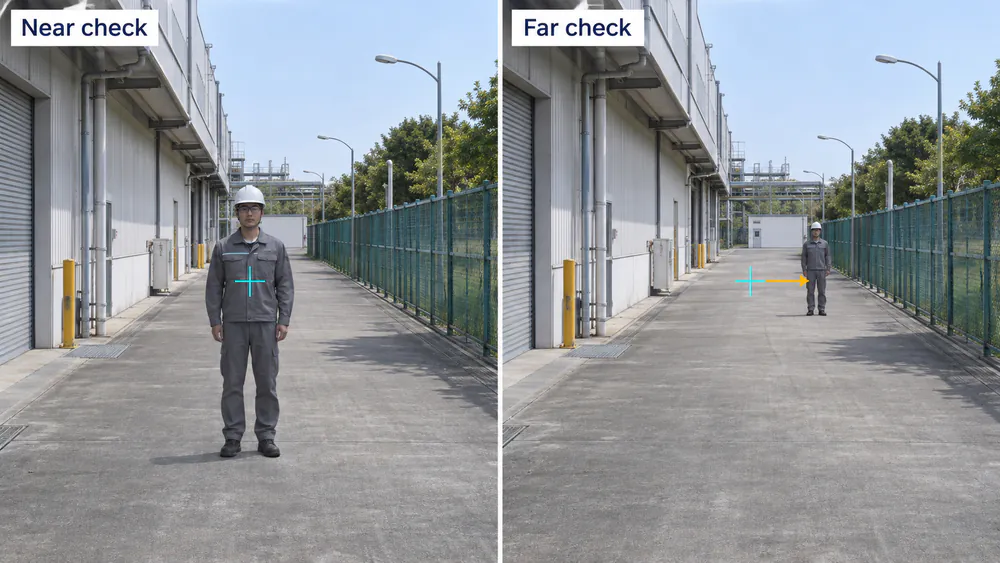
Check known positions across the required area; a successful near check does not establish alignment at every distance.
For a known-position pointing test, use a platform-supported diagnostic coordinate or a surveyed reference as appropriate. If the radar does not maintain a stationary-person track, do not require a person standing still to remain in the object list. A stationary reference can check camera geometry without proving stationary-target detection. Validate live radar-driven tracking separately with moving targets.
Axis’s PTZ calibration guidance similarly highlights the choice of reference positions and the effect of site topography. Use those as general engineering considerations; follow the point count and procedure required by your own control application.
After recalibration, test positions that were not used to create the calibration. Record horizontal and vertical error separately. If the result is good only near the chosen references, investigate the model, coordinate mapping and site coverage rather than repeatedly moving the same calibration points until one view looks acceptable.
4. If pointing works but moving targets lag, trace the timing
A walking target can move between the radar measurement, its reception by the platform, the camera command, the PTZ movement and the displayed video. A fast nominal radar update rate does not describe the delay through that complete sequence.
Compare the same target at corresponding times. If the camera physically follows behind the person, inspect the age of the position used for pointing and the camera’s response. If the recorded view centres the person but appears late on the operator’s screen, inspect video delivery and display buffering before changing the pointing calibration.
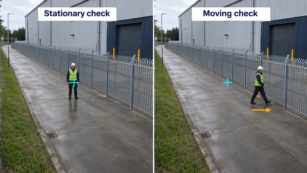
Evaluate pointing geometry first, then compare moving-target position and camera response at corresponding times.
Where the system exposes them, compare measurement or receive timestamps, selected-target updates, command times, PTZ feedback and video timestamps. Confirm clock alignment before subtracting timestamps from different devices. If those records are unavailable, use synchronised reference recordings and a documented test sequence to identify the stage where the lag becomes visible.
Check for queued old commands, unnecessary processing or smoothing, excessive network delay and camera movement limits. A controller repeatedly executing stale positions can keep aiming behind a person even though newer radar data have arrived.
Use the application’s supported tracking settings and examine one change at a time. Increasing camera speed indiscriminately can introduce overshoot or oscillation. Predictive pointing, where supported, also needs evaluation during turns and stops; it is not a universal correction for bad timing.
The Axis tracking considerations identify latency as a performance factor. Your acceptance result should come from the actual radar, controller, camera and network arrangement.
5. If zoom loses the person, keep useful framing margin
Establish pointing with a wide view before requesting a tight close-up. A wider view may hide a small angular error that becomes obvious at higher zoom. It also leaves more room for movement while the camera responds.
Check whether the person leaves the frame because the camera points incorrectly, because zoom narrows the view too early, or because focus and image quality make the person difficult to see. These observations need different corrections.
- Consistent off-centre position: revisit calibration across the required area.
- The person moves out during the zoom operation: review zoom timing, tracking delay and the framing margin supported by the application.
- The person remains in the frame but becomes blurred: investigate focus, exposure and camera settings.
- The person disappears behind a building or vegetation: review the camera’s line of sight; a correct radar position cannot make the camera see through the obstruction.
Define whether the project needs general visual verification or a more detailed image, then test that requirement at representative distances and lighting conditions. Do not assume that one zoom setting suits every target distance. The perimeter radar placement guide helps review obstructions and observation points before compensating with control settings.
6. If the camera switches between people, inspect target selection
A PTZ camera has one instantaneous viewing direction. Multiple radar tracks do not mean that one camera can obtain a close-up of every person at once. The control application needs a clear policy for which target or group to follow and when to switch.
Record the selected target ID alongside the camera motion. If that selection changes each time the camera turns, inspect priority, target-hold and switching rules. If selection remains constant while the camera jumps, inspect pointing, command ownership and the underlying position updates.
Review the intended treatment of a higher-priority event, a temporary track loss, a person leaving the permitted area and an operator taking control. Test the supported return and reacquisition behaviour. Avoid solving excessive switching by filtering out people that the project still requires the system to detect or assess.
A changed radar ID can reflect a track ending and a new one being created. It is not a permanent personal identity. The radar object-tracking explanation covers that distinction. Where several radars share a camera, confirm how the platform distinguishes their observations and arbitrates camera control.
If switches are driven by repeated or unnecessary alarm events, review the perimeter alarm troubleshooting workflow as well as the camera-control policy.
7. Verify the correction with a repeatable test
Save the original configuration and the problem recording. Agree which routes, pointing tolerance, acquisition behaviour, framing and event priorities the project needs. Then make one relevant adjustment and repeat the test.
| Test | Verify | Retain |
|---|---|---|
| Known-position pointing | Near, far and lateral locations align within the agreed limits | Reference positions, zoom state and horizontal/vertical offsets |
| One person walking in both directions | Acquisition, framing and lag through the required section | Reference recording, radar updates and camera video |
| A person turning or changing pace | Settling, overshoot and supported reacquisition behaviour | The continuous before-and-after sequence |
| Two people and priority changes | Selection follows the agreed policy without unintended switching | Selected-target history, event priorities and camera movement |
| Normal operating conditions restored | Operator override, patrol and return behaviour work as intended | The final configuration and test outcome |
Inspect the complete passage, including the interval before the person is centred. A good still frame at the end does not establish that the system acquired the correct target in time. Retest any other routes affected by the change, and keep the unsuccessful cases for diagnosis.
8. What to confirm for an MSR-S200 camera-linked project
The MSR-S200 perimeter security radar provides target position and motion information over Ethernet using TCP. A connected platform can use those data to support camera cueing and visual verification. The platform and camera integration determine the calibration workflow, commands and target-selection behaviour.
Before treating a radar and PTZ combination as ready to deploy, confirm the radar data interface, camera model and control method, coordinate mapping, required software and supported event workflow. Ethernet connectivity alone does not demonstrate plug-and-play PTZ compatibility. Do not assume native ONVIF control, camera autotracking or a specific vendor’s calibration feature is provided by the radar.
For a review, prepare the pole locations and heights, site layout, camera model, control-platform version, firmware and a short synchronised problem recording. Include whether known-position tests work, which distances fail, the zoom state and whether the selected target changes.
The perimeter security solution describes the role of radar information in verification and response. You can send the radar and camera arrangement for technical review to establish the interface and test requirements for your project.
Correct the earliest stage that disagrees with the reference: source position, camera pointing, timing, framing or target selection. Then confirm the result across the required area and operating conditions.