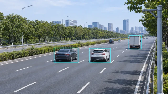

Freeway entrance ramps, expressway junctions and tunnel approaches require vehicles from different paths to converge within a limited distance. When mainline vehicles are travelling at high speed and entering vehicles have insufficient acceleration distance or restricted sight lines, drivers may have little time to recognize a developing conflict.
A ramp merge warning system monitors vehicles on the mainline and entrance ramp, evaluates their movement toward the merge area and activates roadside warnings when predefined risk conditions are detected.
Radar is particularly useful in this application because it can provide target-level distance, speed, direction and trajectory data without cutting the pavement. However, an effective system requires more than installing a speed sensor beside the road. Sensor coverage, target association, warning logic, sign placement and field validation must all be designed around the geometry of the merge area.
What Is a Ramp Merge Warning System?
A ramp merge warning system is an intelligent transportation system that provides drivers with real-time information about vehicles approaching a merge point.
A typical system includes:
- Mainline vehicle detection
- Entrance-ramp vehicle detection
- Multi-target tracking
- Vehicle speed and position measurement
- Conflict-risk assessment
- A roadside controller
- Flashing beacons or variable message signs
- Communication and system-monitoring equipment
The system may warn mainline drivers that vehicles are entering from the ramp, warn ramp drivers that a mainline vehicle is approaching, or provide coordinated warnings to both traffic streams.
The purpose is to improve situational awareness. It does not assign right of way, control the vehicle or guarantee that a collision will be avoided.
Why Ramp Merge Areas Create Conflict Risk
Merging traffic produces interactions that are different from ordinary lane-following traffic.
Speed differences
Vehicles entering from a ramp may be travelling substantially slower than vehicles on the mainline. Mainline drivers may need to decelerate or change lanes, while ramp drivers must identify a suitable gap and accelerate.
The FHWA notes that insufficient acceleration distance and large speed differences can contribute to rear-end, lane-change and sideswipe conflicts around freeway merge points.
Limited sight distance
Curved ramps, retaining walls, vegetation, bridge structures and tunnel portals can prevent drivers from seeing approaching traffic early enough.
A dynamic warning can provide information before the conflicting vehicle becomes directly visible.
Short merging distance
Some existing interchanges do not provide enough distance for comfortable acceleration and lane changing. Closely spaced entrance and exit ramps may also create weaving movements.
Traffic platoons
Several ramp vehicles arriving together can disrupt mainline traffic more severely than individual vehicles. Mainline vehicles may brake or change lanes abruptly to create space.
Congestion and unstable traffic flow
As mainline traffic approaches capacity, small disturbances can cause rapid speed reductions. Warning logic designed for free-flow conditions may therefore need to operate differently during congestion.
How the System Works
A radar-based ramp merge warning system generally performs five stages.
1. Detect vehicles
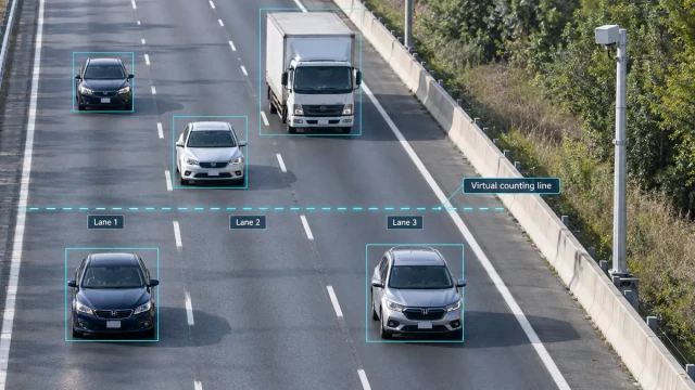
Radar sensors monitor defined zones on the mainline and ramp. Each detected vehicle may be represented by distance, angle, radial velocity and signal characteristics.
2. Create and maintain tracks
Successive detections are associated with individual vehicles. The system assigns track IDs and estimates position, speed, direction and trajectory over time.
Stable tracking is important because conflict assessment must distinguish between several vehicles approaching the merge area simultaneously. See our explanation of radar object tracking for more detail.
3. Predict movement toward the merge point
The controller estimates when relevant vehicles may reach the conflict area. The calculation can consider:
- Distance to the merge point
- Vehicle speed
- Acceleration or deceleration
- Travel direction
- Lane or approach path
- Mainline traffic conditions
- Duration of the predicted conflict
A simple system may use presence and speed thresholds. A more advanced system can use target trajectories and estimated arrival times.
4. Evaluate conflict conditions
A warning should not be activated merely because vehicles are present on both roads. The algorithm must determine whether their projected movements create a meaningful conflict.
Possible inputs include:
- Predicted arrival-time difference
- Relative speed
- Available merging gap
- Mainline vehicle proximity
- Ramp vehicle movement
- Traffic queue status
- Track confidence
- Persistence of the risk condition
There is no universal threshold suitable for every site. The operating logic must be calibrated according to road geometry, posted speed, sensor accuracy, warning-sign location and local traffic behaviour.
5. Activate and clear the warning
When the risk criteria are satisfied, the controller activates a flashing beacon, dynamic sign or other roadside warning device.
The warning should remain active long enough to be understood but should clear when the conflict has passed. Hysteresis, minimum activation time and track persistence can prevent rapid flashing caused by measurements moving around a threshold.
Ramp Warning and Ramp Metering Are Different
A ramp merge warning system provides information about a developing traffic condition. It normally does not regulate how frequently vehicles enter the mainline.
A ramp meter uses a traffic signal to control ramp entry. Traffic-responsive ramp metering may use mainline speed, volume and occupancy data to select an appropriate release rate.
The two systems can be used independently or integrated:
- Warning only: alerts drivers to approaching traffic
- Metering only: controls ramp entry rate
- Integrated operation: detection data supports both warning and ramp control
The FHWA describes ramp metering as a method of releasing vehicles in a controlled manner according to the mainline’s ability to accept traffic. A warning system should therefore not be presented as equivalent to ramp metering.
Why Radar Is Suitable for Ramp Monitoring
Radar can monitor vehicles without embedding sensors in the pavement. Depending on the radar and installation geometry, it can provide:
- Vehicle presence
- Target distance
- Vehicle speed
- Direction of travel
- Lane or position
- Multiple simultaneous vehicle tracks
- Trajectory data
Compared with a basic point detector, target-tracking radar can observe vehicle movement across a defined area rather than reporting only that a vehicle passed one detection line.
This distinction is important at a merge because the system may need to determine which vehicle is approaching the conflict point, how fast it is moving and whether the track remains within the relevant approach path.
Radar can also complement video. Radar supplies distance and velocity data, while a camera provides visual context and verification. The relationship is explained further in radar-video fusion for roadside monitoring.
Sensor Placement and Detection Zones
Sensor placement should be based on the complete warning timeline.
The detection zone must provide enough distance for:
- The radar to detect and confirm a vehicle.
- The controller to calculate the risk.
- The warning device to activate.
- The driver to notice and understand the warning.
- The driver to respond before reaching the merge area.
Installing a sensor too close to the conflict point may provide accurate data but insufficient warning time. Installing it too far away may increase the influence of lane changes, speed variation and unrelated traffic.
Mainline monitoring
The mainline sensor should cover the lane or lanes that interact with entering traffic. Where vehicles can change lanes before the merge point, the system must define how lane changes affect the conflict calculation.
Ramp monitoring
The ramp sensor should detect vehicles early enough to determine whether they are moving toward the merge point. Curvature, grades, barriers and nearby structures may restrict the field of view.
Overlapping coverage
If several sensors are used, overlapping tracks must be associated correctly. Otherwise, the same vehicle may appear as two targets or disappear when passing from one coverage zone to another.
Warning Device Placement
A technically correct conflict decision has limited value if drivers cannot see or understand the warning.
Warning devices should be positioned according to:
- Available sight distance
- Approach speed
- Road curvature
- Driver decision point
- Existing signs and visual clutter
- Sunlight and nighttime visibility
- Maintenance access
- Applicable traffic-control standards
The message should be concise and directly related to the expected action. Sign wording, colour, beacon operation and installation location must comply with the standards of the jurisdiction where the system is deployed.
Data Outputs and System Integration
A ramp merge warning system may need to communicate with:
- Roadside warning signs
- Traffic signal or ramp-meter controllers
- Variable message signs
- Traffic management centres
- CCTV or PTZ cameras
- Edge-computing devices
- Event logging platforms
- Maintenance-monitoring systems
Useful output data can include:
- Track ID
- Timestamp
- Vehicle speed
- Target coordinates
- Direction
- Detection zone
- Conflict status
- Warning state
- Device health
- Communication status
Interfaces should clearly define units, coordinate systems, update rates and how lost or uncertain tracks are handled.
Designing the Warning Logic
Warning logic should balance two competing risks.
If it is too sensitive, the system may activate when no meaningful conflict exists. Frequent unnecessary warnings can reduce driver trust.
If it is not sensitive enough, a relevant conflict may not produce sufficient warning time.
Design should therefore consider:
Time to the conflict area
Estimated time to arrival can be more useful than distance alone because two vehicles at the same distance may be travelling at very different speeds.
Arrival-time separation
The difference between the predicted arrival times of the mainline and ramp vehicles can indicate whether their paths may overlap.
Relative speed
A large speed difference may require additional attention even when the initial separation appears acceptable.
Track stability
Warnings should normally rely on confirmed tracks rather than a single radar detection.
Congestion mode
During slow or queued traffic, ordinary high-speed thresholds may generate continuous alarms. The controller may need different logic for free-flow and congested conditions.
Fail-safe behaviour
The system should define what happens when sensor data, communication or power becomes unavailable. A technical fault should not be presented as a confirmed safe condition.
Selecting a Radar for the Application
Maximum detection range is not the only selection criterion.
Important specifications include:
- Required coverage length and width
- Minimum detection range
- Speed measurement performance
- Position accuracy
- Angular resolution
- Multi-target capacity
- Update rate
- Track output
- Environmental protection
- Mounting requirements
- Communication interfaces
- Operating temperature
- Diagnostic functions
The radar must also separate vehicles travelling close together. For an explanation of range, velocity and angular separation, see radar resolution explained.
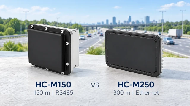
The HC-M250 traffic radar can be evaluated for traffic applications requiring target-level vehicle detection and tracking. Final suitability depends on the required coverage, installation geometry and system interface.
Installation Challenges
Road curvature
A curved approach changes the relationship between vehicle velocity and radar line of sight. Coverage and speed output must be checked across the relevant road section.
Barriers and structures
Guardrails, concrete barriers, signs, bridge components and retaining walls can block or reflect radar signals.
Large vehicles
Trucks may temporarily obscure smaller vehicles. The system must be tested with representative traffic rather than passenger cars alone.
Adjacent roads
Vehicles travelling on nearby roads can enter the radar field of view. Detection zones and trajectory filtering should exclude targets that cannot reach the merge point.
Weather and contamination
Radar is generally less dependent on visible light than a camera, but mounting movement, water accumulation, ice or contamination can still affect a complete installation.
Communication delay
If sensors, controllers and signs communicate over a network, total system latency must be included in the warning-time calculation.
Field Testing and Acceptance
Testing should use realistic traffic movements and should cover more than simple sensor detection.
Recommended tests include:
- One ramp vehicle and one mainline vehicle
- Several simultaneous vehicles
- Cars, trucks and motorcycles
- Different approach speeds
- Acceleration and deceleration
- Lane changes near the merge area
- Vehicles stopping on the ramp
- Congested traffic
- Empty-road conditions
- Adjacent-road interference
- Communication interruption
- Sensor or warning-device faults
- Day, night and adverse weather
The test should record:
- Detection probability
- Speed and position accuracy
- Track continuity
- Warning activation time
- Warning clearance time
- False warning frequency
- Missed conflict events
- Communication latency
- System recovery after faults
Thresholds should be adjusted using documented test results rather than informal observation alone.
Typical Applications
Freeway entrance ramps
The system can monitor mainline traffic and entering vehicles where speed differences or limited acceleration distance create operational concerns.
Urban expressway junctions
Elevated roads and dense structures may restrict sight distance at closely spaced ramps.
Tunnel entrances and exits
Walls, curvature and changing visibility may prevent drivers from observing joining traffic early.
Mountain and curved interchanges
Terrain can conceal vehicles approaching from another direction until they are close to the merge point.
Work zones
Temporary lane arrangements and reduced visibility may require traffic-responsive warnings. Sensor mounting and warning logic must match each construction phase.
Industrial and logistics roads
Heavy vehicles entering a higher-speed internal road may benefit from coordinated detection and warning.
Frequently Asked Questions
Does a ramp warning system control the vehicles?
No. It detects traffic conditions and provides a warning. Drivers remain responsible for observing road rules and responding safely.
Is this the same as a ramp meter?
No. A ramp meter controls when vehicles enter a freeway. A merge warning system informs drivers about approaching traffic or a predicted conflict.
Can one radar monitor both the ramp and mainline?
Possibly, but it depends on road geometry, required coverage, radar field of view and obstructions. Some sites require separate sensors.
Can the system use only vehicle speed?
Speed alone is usually insufficient for target-level conflict assessment. Distance, direction, trajectory, lane position and track timing may also be required.
Can cameras replace radar?
Video analytics may detect and classify vehicles, but performance depends on lighting, visibility and camera placement. Radar provides direct motion and distance-related measurements, while cameras provide visual context. A combined system may be appropriate for demanding sites.
Does every simultaneous arrival require a warning?
Not necessarily. The algorithm should evaluate whether the projected trajectories, separation and timing satisfy the configured risk criteria.
Conclusion
A ramp merge warning system converts real-time vehicle measurements into an actionable roadside warning. Radar can provide the distance, speed, direction and target tracks needed to monitor both mainline and ramp traffic, but reliable performance depends on the entire system.
Coverage design, sensor placement, trajectory processing, warning thresholds, sign visibility, communication latency and field testing must be considered together. The final warning logic should be calibrated for the actual road geometry and traffic conditions instead of relying on a universal distance or speed threshold.
When correctly engineered, the system can provide earlier information about vehicles approaching a difficult merge area and support a broader traffic-management strategy.