If a speed camera consistently captures vehicles past the readable part of the image, measure where the vehicle was when the camera exposed the frame. A frame that arrives late can still show the vehicle in exactly the right place. The delay that affects trigger-line placement is the time from the vehicle crossing the configured line to the exposure of the image used for that event.
Once you have measured that delay across the lanes and speeds you need to support, convert it to distance. A vehicle at 100 km/h moves about 2.8 m in 100 ms. Use that displacement to find where a trigger line can sit while keeping the required view inside the camera’s usable capture window.
1. Mark the usable camera capture window
For each lane and direction, mark the upstream and downstream positions where the required image is usable. For a plate camera, check actual plate readability at those positions using the installed lens, exposure and lighting. A vehicle can still be inside the field of view after its plate has become too small, blurred, badly angled or poorly illuminated. Check both day and night and record the limits for each condition. See the Axis license plate capture guide for the optical factors that shape this window.
Measure distance along the lane in the direction of travel. Use a consistent point on the vehicle when you mark the window and time the crossing. If the radar tracks a point within the vehicle body and the camera needs the rear plate, compare those reference points explicitly. The offset can vary with vehicle length and view angle. Treat it as part of the geometry when recording the available margin.
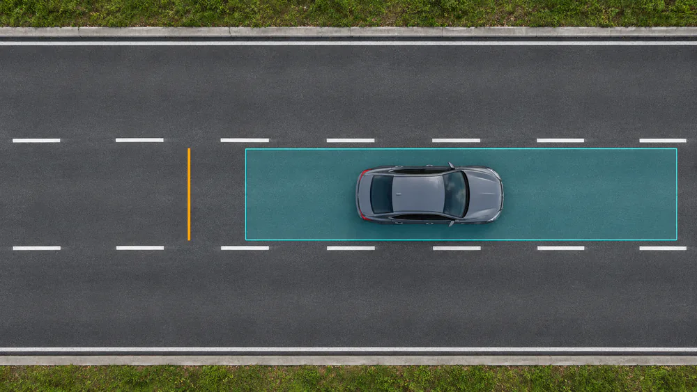
Amber marks the trigger line. Cyan marks the usable capture window downstream in the direction of travel.
2. Record the crossing, trigger and exposure
| Event | What to record |
|---|---|
| Line crossing | Time when the agreed vehicle reference passes a surveyed road mark corresponding to the trigger line. Use calibrated reference video or an independent sensor. Record the radar or controller event timestamp separately when available. |
| Trigger sent | Time of the actual output edge or command send. If you can also log when the camera accepted the trigger, record it separately. Check what each timestamp represents in the device documentation. |
| Image exposure | Exposure time for the frame assigned to that event, using a documented camera signal or timestamp. For a rolling shutter camera, check whether the timestamp describes the full frame or a specific part of the readout and account for the timing at the plate rows if it matters. |
| Frame received | Time the controller received the image. Keep this for investigating delivery delays, including readout, transfer and downstream buffering. |
Subtract crossing time from exposure time to get the total delay that moves the vehicle along the lane. Crossing to trigger sent measures the upstream contribution. Trigger sent to exposure covers delivery of the command and the camera’s response. An acceptance timestamp, when available, helps split that last interval. A radar’s target update interval and a camera’s frame rate are useful configuration details. Measure the assembled system to establish the actual delay.
3. Measure camera trigger latency on a common clock
For a hardware-triggered camera with a documented exposure output, log the trigger edge and exposure signal on two channels of the same instrument. Confirm the signal semantics for the specific camera and mode. That trace measures the interval between the two signals. To include crossing-to-trigger delay, align the independent crossing reference with the trace or record a crossing reference pulse on the same logger. Camera manuals from Basler on acquisition timing and Basler on exposure and line signals show examples of timing stages and signals that can vary by device and configuration.
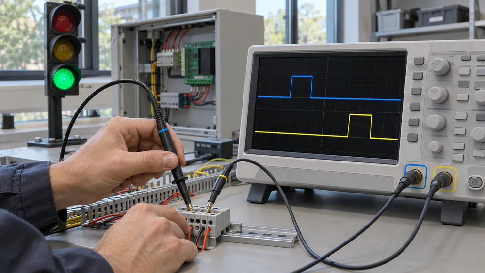
A common time base lets you measure the interval between the trigger edge and a documented exposure signal.
For a software trigger, check the clock offset and drift between the controller and the camera before comparing timestamps. Record whether each camera timestamp refers to exposure, readout or another event. If exact exposure timing is unavailable, calibrated reference video can bound the crossing and estimate the captured position. Record the timing uncertainty. At 60 frames per second, consecutive frames are about 16.7 ms apart, before accounting for synchronization and camera timing.
With buffered video, the event may select a frame that was already exposed. Compare crossing time with the acquisition time of the selected frame and allow the offset to be negative when the system picks a frame from before the crossing. Check the recorder’s selection rule as well as the link delay. An arrival timestamp alone cannot show which road position the selected frame represents.
4. Calculate where to place the radar trigger line
For approximately constant speed through the capture area, use distance travelled (m) = speed (km/h) ÷ 3.6 × delay (s). With distance increasing along the lane, subtract the expected travel distance from the desired exposure position to obtain an initial trigger position. Then check whether the same line works at both ends of the measured displacement range.
Suppose the usable capture window is from 20 m to 25 m along a lane. At 100 km/h, an illustrative measured delay range of 120–180 ms gives a movement range of 3.33–5.00 m. The earliest exposure needs the trigger line at or after 20 − 3.33 ≈ 16.67 m. The latest exposure needs it at or before 25 − 5.00 = 20.00 m. A line at 18.33 m puts the exposure at about 21.67–23.33 m under those example conditions, leaving roughly 1.67 m on either side before allowing for measurement and position uncertainty.
Repeat the calculation with actual speed-and-delay pairs for each lane and direction. Compare the resulting acceptable line positions, including a margin for geometry, alignment and timing uncertainty. If those positions have no overlap, a fixed line cannot cover the tested cases. Look for the stage causing variability, check whether the optics can deliver a wider usable window, or evaluate lane-specific or speed-based trigger placement if the controller supports it. Commission the chosen line with a new set of passes and confirm that the radar has a stable track at the line.
5. Diagnose late captures and wrong-vehicle images
| Field symptom | First check |
|---|---|
| The correct vehicle is consistently beyond the window | Verify the road reference and repeat the delay measurement. If the delay is stable, check whether an upstream line position brings the exposure into the window across the tested speed range. |
| Captures become late or disappear during bursts | Log command send, camera acceptance and exposure under closely spaced events. Check controller queuing, camera busy behaviour and how the system handles dropped or rejected triggers. |
| Another vehicle appears when two lanes trigger together | Compare event ID, lane, direction and track ID with the image assignment. Check whether a shared trigger path or a frame selection rule is pairing the wrong records. See radar–video target association. |
| The frame is correctly positioned but unreadable at night | Check exposure duration, illumination, focus and the usable window under darkness. Test again with representative vehicle speeds. |
| The image appears late in the application but the vehicle is correctly positioned | Compare exposure with frame receipt to isolate readout, transfer, encoding or application buffering. |
When both devices report a speed and those values disagree, check that they describe the same vehicle and measurement interval. The radar and camera speed verification guide covers that separate test.
6. Validate the capture window with real traffic
Start with isolated vehicles to verify each lane’s geometry and establish a baseline. Then test the expected speed range, short headways, side-by-side traffic, different vehicle lengths and the illumination conditions the site must support. Log the lane and direction, vehicle or track reference, speed, crossing, trigger and exposure times, exposure position and whether the required image is usable. Include passes without an assigned frame in the test record.
Use the observed delay spread and the proportion of events with a usable image of the correct vehicle inside the window. Report missing images, out-of-window images, unreadable plates and incorrect associations separately. Agree the acceptance criteria for the installation before the test. Repeat the checks after changes that affect timing or geometry, such as trigger mode, controller logic, camera aiming or mounting.
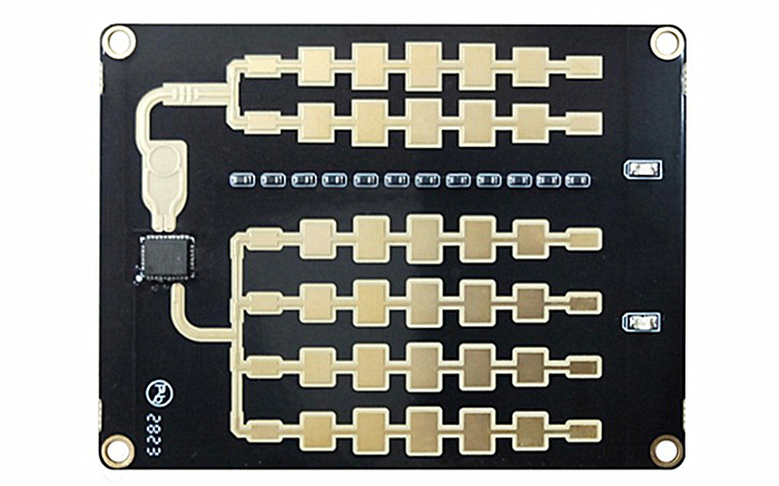
In an integrated speed enforcement workflow, the HC-M150 multi-lane traffic radar can provide vehicle track and position data to the host via RS485. The host applies the configured event logic and uses the camera’s supported capture interface. For the radar side of that connection, see the HC-M150 RS485 integration guide.