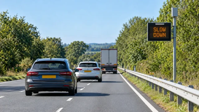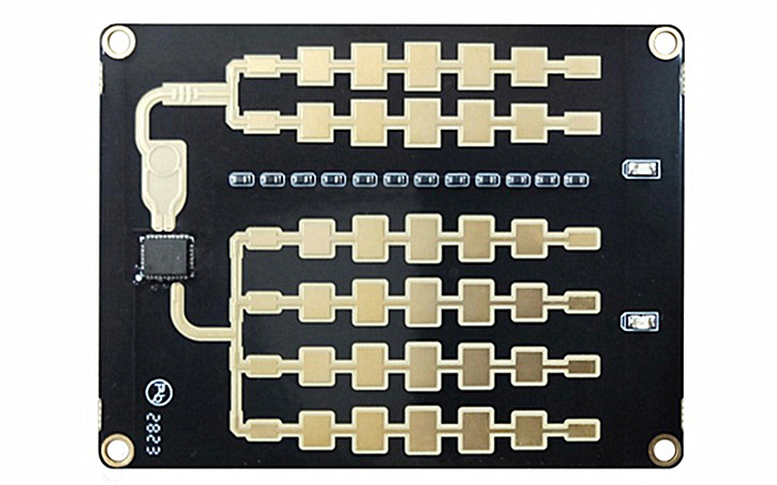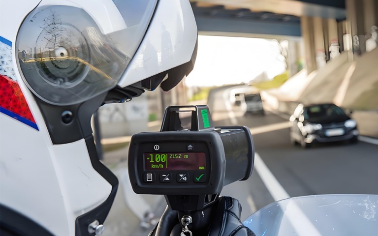
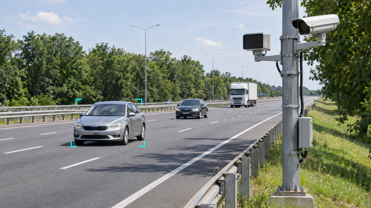
When radar and a camera display different speeds, first identify where each number comes from. Then match the same vehicle, measurement time and road position before judging the difference. A camera can display a radar-supplied value rather than make an independent measurement. A second instrument may also report a different time interval or speed quantity.
Start with one clearly identifiable passage and preserve the source records. This guide gives a practical order for investigating mismatches, including vehicle association, timing, installation geometry and reference-device limitations. The broader radar-video fusion guide explains how the two sensing systems can be associated; here the task is to establish whether their speed records are actually comparable.
1. Establish whether the two readings are independent
Ask the integrator to identify the speed source used by each display and saved event. Trace the value back to its record, not just its on-screen label. For example, AXIS Speed Monitor can display radar speed in camera video. This illustrates why a number on an image is not necessarily video-derived speed; it does not establish compatibility with another manufacturer’s radar.
| What you are comparing | Confirm first | What the comparison can establish |
|---|---|---|
| Radar output and a radar-fed camera overlay | Source object, source timestamp and processing used for the overlay | Whether the integration carries the intended value to the intended vehicle |
| Radar and independent video speed estimation | Scene scale, timing, tracked vehicle and measurement interval | Agreement between two methods under aligned conditions |
| Radar and an in-vehicle GPS/GNSS receiver | The specific test vehicle, recorded sample times, receiver conditions and output behaviour | A comparison with that receiver, whose suitability still needs establishing |
| Radar and the vehicle dashboard | Display behaviour, instrument condition and time of observation | A preliminary cross-check, not automatically a calibrated reference |
| Two radar instruments | Which vehicle each selected, their geometry and reported speed definition | Agreement only after target selection and measurement conditions are matched |
If both displays use the same radar record, a disagreement should first lead to checks of selection, timestamps, units, averaging and display handling. It is not an independent test of radar accuracy. Record whether a displayed value is live, held from an earlier update or taken from a saved event.
2. Match the physical vehicle before comparing its speed
Do not pair records solely because two numbers look close. Use lane, position, direction, passage order and continuous video to establish the correspondence first. Where available, follow the radar ID across the relevant interval, while remembering that an ID identifies a track rather than a permanent vehicle identity.
Review the moments before and after the measurement, especially for adjacent-lane cars, close following and a smaller vehicle beside a truck. Confirm that the image box, radar object and saved event all refer to the same passage. A system can draw a plausible box around one car while attaching another object’s speed.
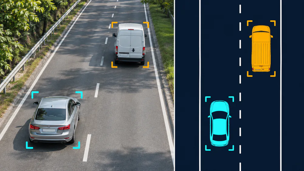
Use vehicle position, lane and continuous history to establish the pair before comparing speed values.
If a mismatch occurs mainly in multi-vehicle traffic but not in isolated passages, association deserves early attention. Use the multi-vehicle separation field checks to investigate merging, occlusion and ID changes. A single-speed sensor also needs its selection rule checked: the reported speed is not automatically the speed of the car nearest a camera marker.
3. Align the source time, not just two display screens
Determine what each timestamp means: sensor observation, host reception, camera exposure, event creation or display refresh. Matching two arrival times at a computer is not the same as matching the original observation times. Record the available clock relationships and processing delays before selecting corresponding samples.
A useful check is a clearly identifiable vehicle crossing a fixed road reference. Compare its source trajectory with the video sequence and inspect timing on more than one passage. A common shift across several moving vehicles points toward timing or processing, while a mismatch isolated to one vehicle may require a different investigation.
Separate record time from smoothing and holding behaviour. A display may update less frequently or average several observations. Even synchronised clocks do not make differently averaged values equivalent. The HC-M150 data-integration guide helps distinguish live object records from measurement-line information and interval statistics; a lane’s average speed is not the reference for one selected vehicle.
4. Compare the same position or the same measurement interval
One vehicle can legitimately have different speeds at different road positions. Identify where the radar value was sampled and where the other method measured. A picture captured at position B may carry a speed selected earlier at position A. That can be an intended event design, but it must be understood before comparing numbers.
For independent video measurement, establish the actual road distance and elapsed time used. Distance divided by time gives an average over that interval. Comparing it with a radar sample taken at one endpoint is not equivalent when the vehicle changes speed. Start with passages that are reasonably steady through the common review section, then assess accelerating or braking passages separately.
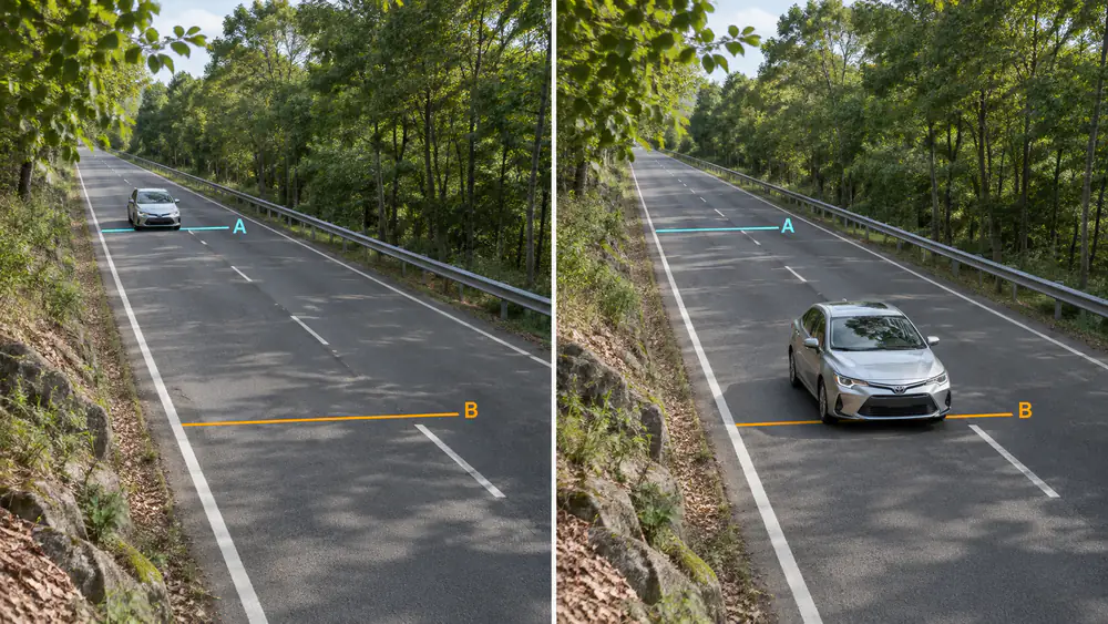
A record selected at A and a picture captured at B need not represent the same measurement position or instant.
Video-derived measurement also needs a valid relationship between image displacement and road distance. Camera movement or a changed scene scale requires a calibration review. Research on traffic-camera calibration for vehicle speed measurement illustrates the importance of scene geometry. Do not infer metres from arbitrary image pixels or assume a nominal frame rate proves the elapsed time of an exported clip.
5. Confirm speed meaning and compensation before changing angles
Confirm units and whether the output represents line-of-sight speed, a coordinate velocity component, a road-direction estimate or an already compensated result. For a stationary sensor reporting uncompensated radial speed, the magnitude follows the projection:
|vradial| = vroad × |cos θ|
Here θ is the angle between the vehicle’s motion and the radar line of sight, including the actual spatial geometry. It is not automatically the number printed on a mounting bracket. This follows the distinction between velocity and relative radial speed. This stationary-sensor relation is not a moving-patrol-radar correction procedure.
Do not apply an extra cosine correction to a field that is already compensated or represents something other than radial speed. Likewise, do not treat one X/Y component as road speed without confirming the coordinate convention. For HC-M150 installations, check the actual mounting and alignment configuration against the installation and lane-calibration guide and the delivered output definition.
If a discrepancy changes with lane or road position, review geometry and association before adding a fixed offset. Change one documented setting at a time, retain the original configuration and recheck the required near and far sections. Fitting a correction to one pass can conceal the cause elsewhere.
6. Establish whether the reference is suitable for the test
A dashboard or phone display can help reveal an obvious discrepancy, but cannot automatically establish which device is wrong. Identify the reference method, documented performance, installation, update behaviour and usable operating conditions. Where a formal accuracy decision is required, use a reference and procedure suitable for that decision, including its calibration status and uncertainty.
For GPS/GNSS, use recorded receiver output with usable timing information rather than a photograph of a changing screen. GPS.gov explains that receiver speed accuracy depends on reception and receiver factors; the accuracy of the signal in space is not a guarantee for a particular phone or navigation device. Examine how a receiver behaves during the actual passage, especially when the comparison changes with acceleration or obstruction.
For another radar, establish which vehicle it observes and what speed it reports. For video, establish scale and timing. If the reference has not been characterised well enough, retain the finding as a disagreement between two systems rather than declaring the radar out of specification.
7. Classify the pattern across matched passages
For each accepted pair, retain both original values and calculate the signed difference: Δv = vtest − vreference, after putting them in the same units and aligning their meaning. Keep vehicle, lane, time, position or interval, and configuration with the pair. Preserve rejected or unmatchable passages separately so they do not disappear from the test record.
| Repeated pattern | Investigate next | Avoid this shortcut |
|---|---|---|
| Disagreements mainly during crowded passages | Vehicle association, occlusion and selection of the source record | Averaging unrelated vehicle pairs |
| Disagreement grows during acceleration or braking | Time alignment, measurement positions and averaging intervals | Calling every difference an accuracy failure |
| Disagreement depends on lane or road position | Geometry, video calibration and lane association | Applying one offset to all lanes |
| A repeatable scale difference remains in aligned steady passages | Units, speed-field definition, compensation and reference scale | Changing calibration before confirming the data meaning |
| A repeatable difference remains after comparison conditions are verified | Documented functional checks and a suitable reference test with the supplier | Adjusting the instrument until it matches an unverified display |
Do not let positive and negative differences cancel in a single average. Review spread, lane dependence and association failures as well as signed bias. Agree the acceptance criterion and reference method before judging the results; there is no universal acceptable difference for every sensor, speed range and application. For a speed-enforcement integration, an engineering cross-check does not replace the applicable verification procedure.
8. Send a complete comparison, not just two numbers
For an HC-M150 multi-lane radar project, retain the mounting layout, firmware and configuration, continuous reference video, original received object records, event records and reference-device information. Identify the vehicle and exact interval to review, what each speed represents, and how the time bases and road positions were aligned.
Include several repeatable problematic passages and correctly handled ones. If extra objects or misplaced coordinates complicate the pairing, use the false-target and alignment checks first. Preserve configuration changes with each recording rather than sending an unexplained screenshot.
The next action should follow the evidence: correct integration when the intended source value is attached incorrectly; correct timing or geometry when the observations are not comparable; arrange a suitable device check when a repeatable discrepancy remains under verified conditions. That sequence makes the comparison useful without assuming either radar or camera is automatically the reference truth.